What To Do
1a. Make a machine that is controlled from a computer or phone.
1b. Use at least one stepper motor.
2. How can you calibrate motor position (i.e. guarantee the "home" position)?
What I Did
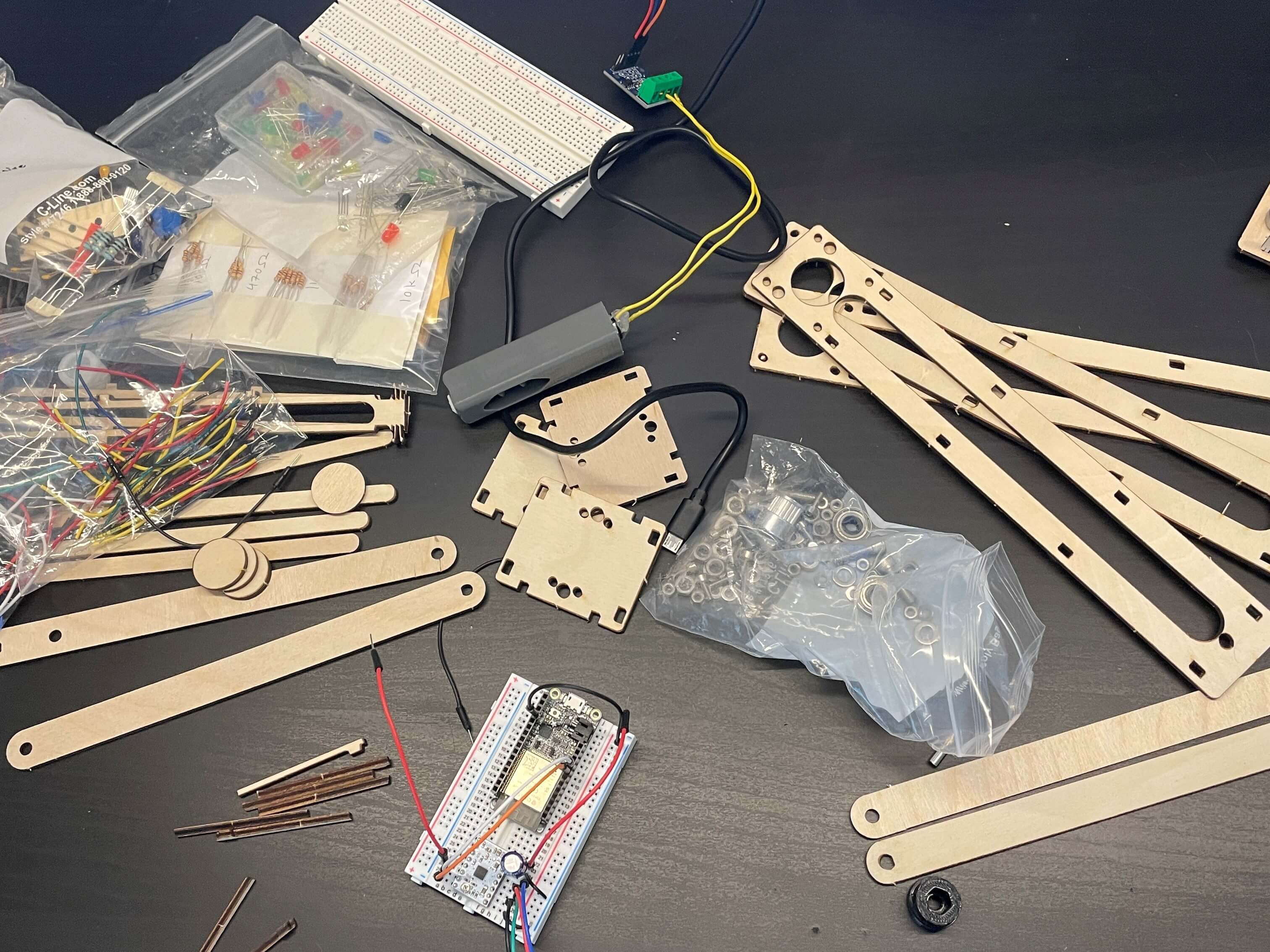
I made various machines using Nema 17 stepper motors and the lazer-cut machine parts. The building part of the machines wasn't really hard, as it was just connecting snap-fit pieces. The coding part, however, was much harder because I used a stepper motor library called AccelStepper to control the stepper motors. I looked over. the class examples quite a bit to learn how the AccelStepper library worked. Once I figured out how to use some basic movement functions of the AccelStepper library, I started building my own machines.
For tutorials I referenced, I looked at quite a few, because I was confused on how to use the stepper motors. One of the best ones was looking at the AccelStepper Class Reference page, as it had a list of all the functions and what they do. I quickly glanced over the Stepper Motor Basics page on Arduino's forums. I also looked at two Google Groups discussions, one for the RunSpeedToPosition function and another for currentPosition function, both of which are functions of the AccelStepper library.
I watched two YouTube video tutorials about controling stepper motors. They were both really good help as they teach the basics of controling a stepper motor and using it to turn a timing belt for an axis. But, because neither was exactly what I needed, I was relatively on my own for most of this assignment.
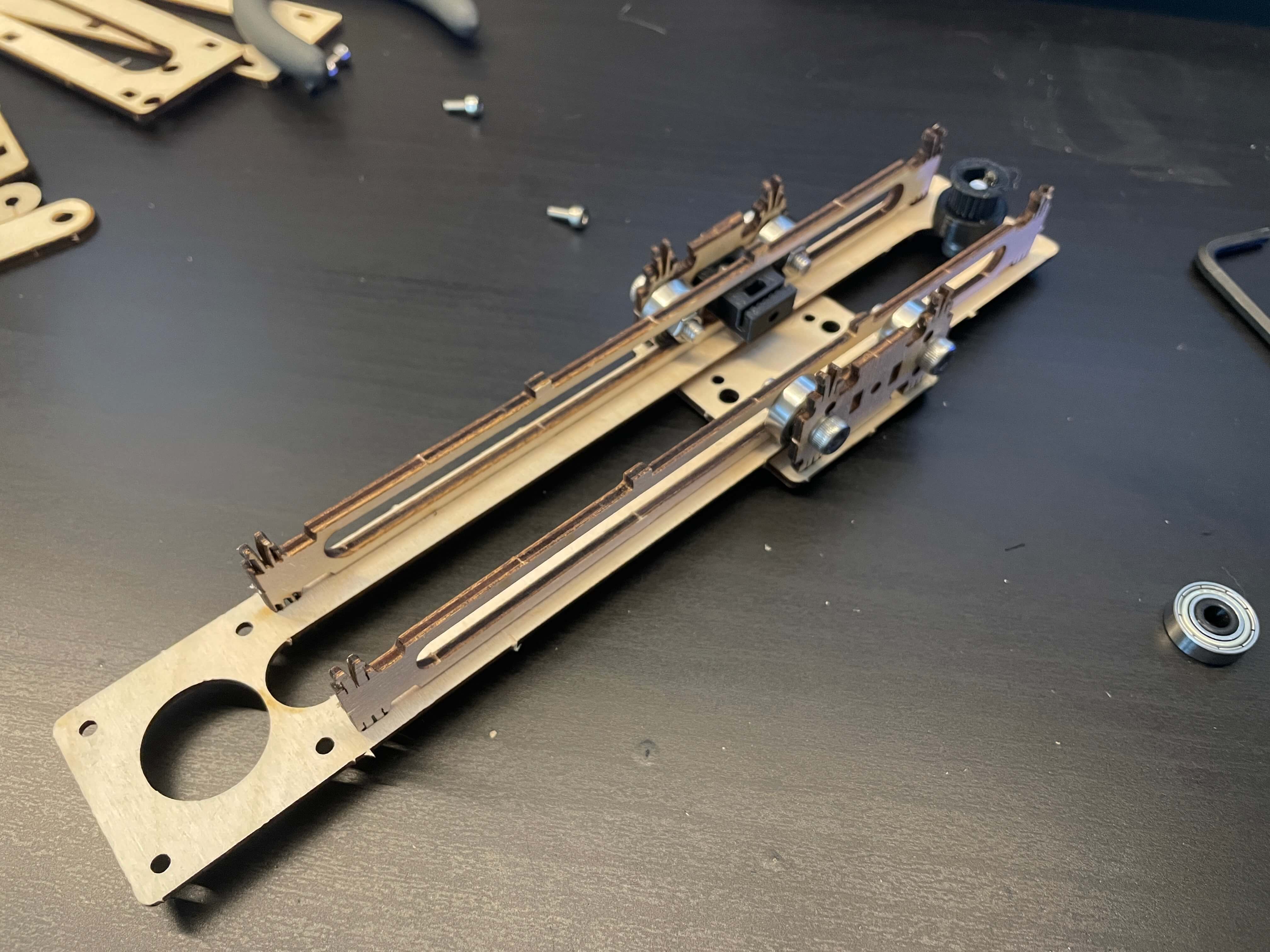
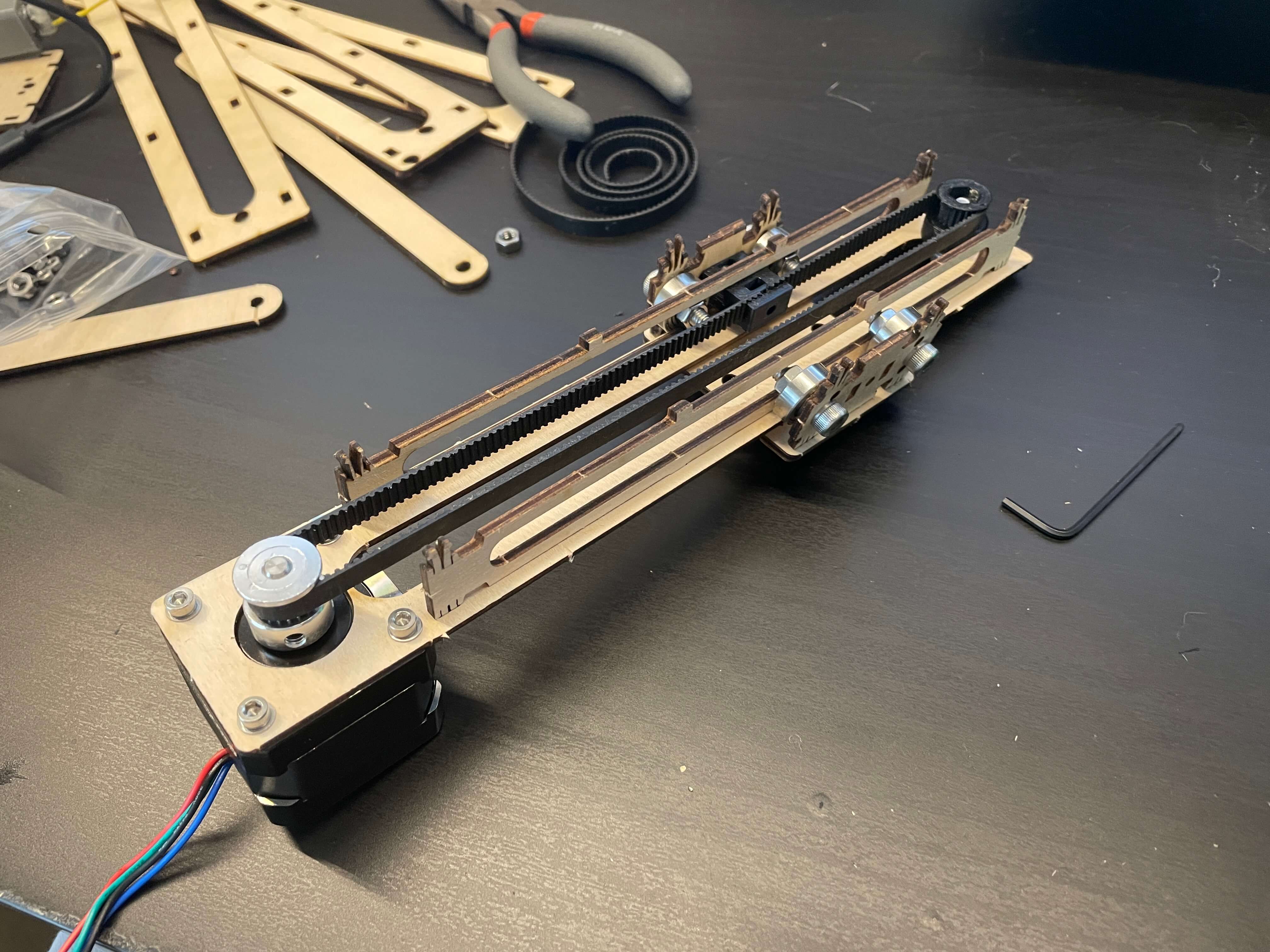
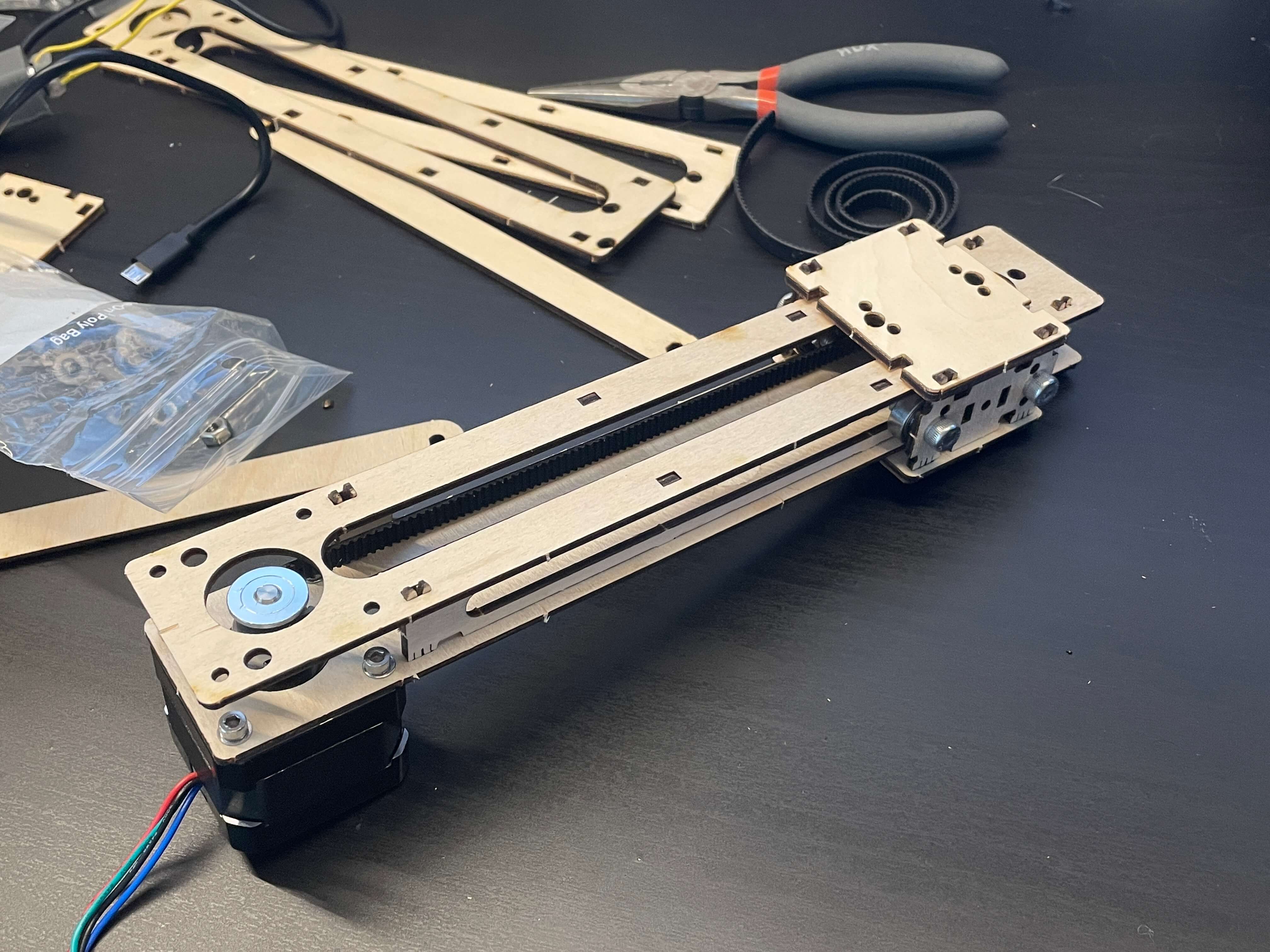
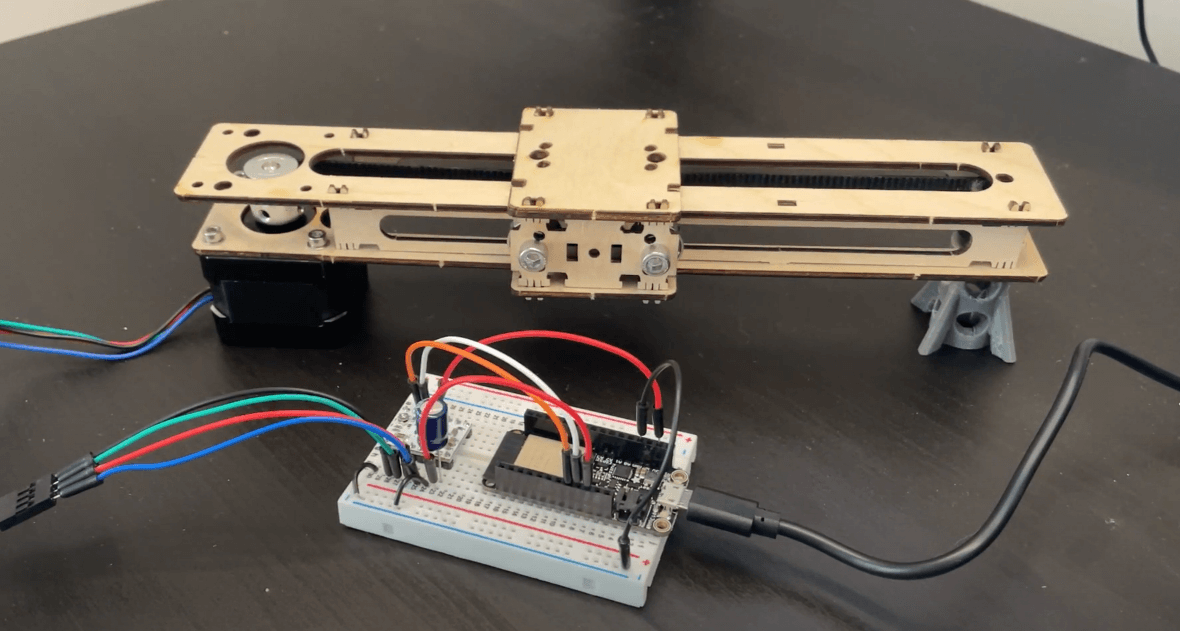
I also had to actually make the machine components using the lazer-cut parts from the kit. The pictures below show the process of making one axis with a carriage that moves using a timing belt hooked up to a stepper motor.
Class Stepper Motor Examples
These are two of the class examples we did. The first one just slides the carriage to random positions using random speeds and random acceleration, so no human control. The second one I modified by adding a left and right button to control the stepper motor turning in either direction.
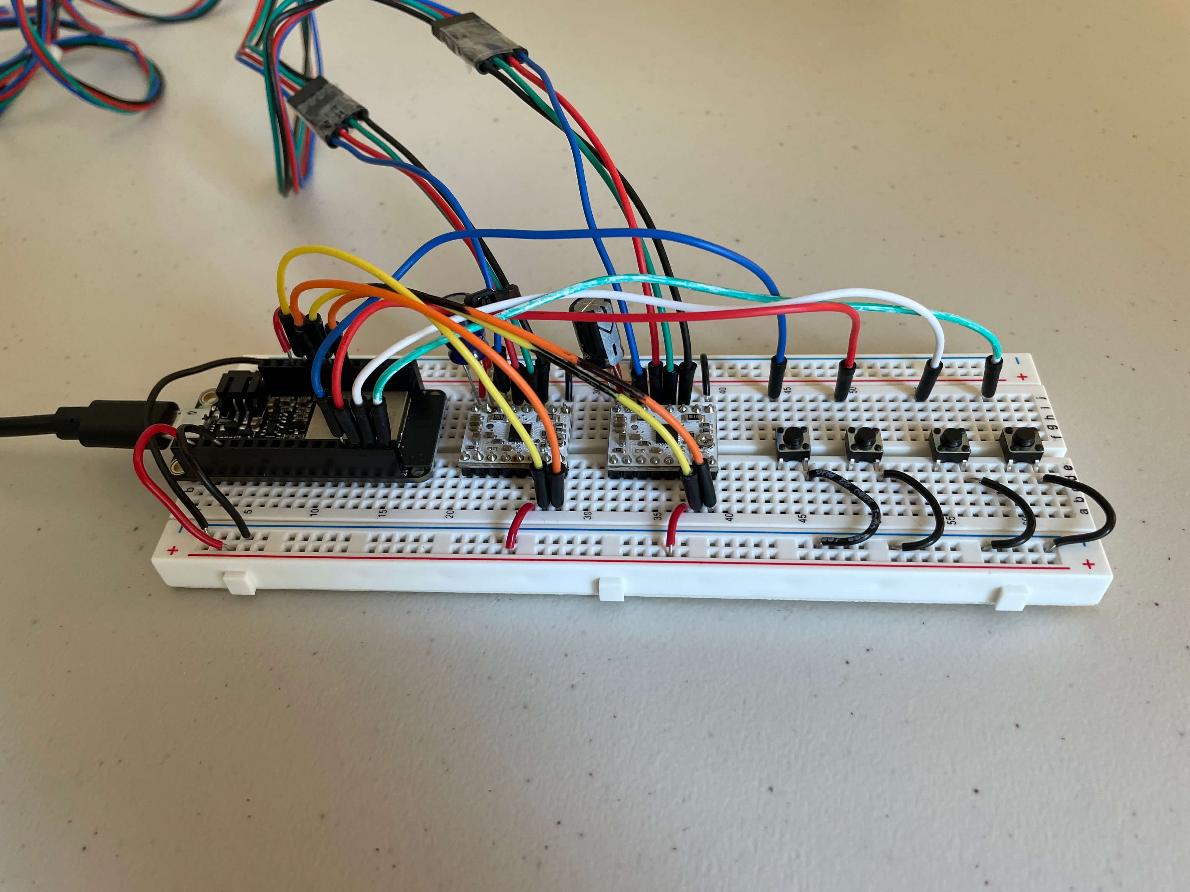
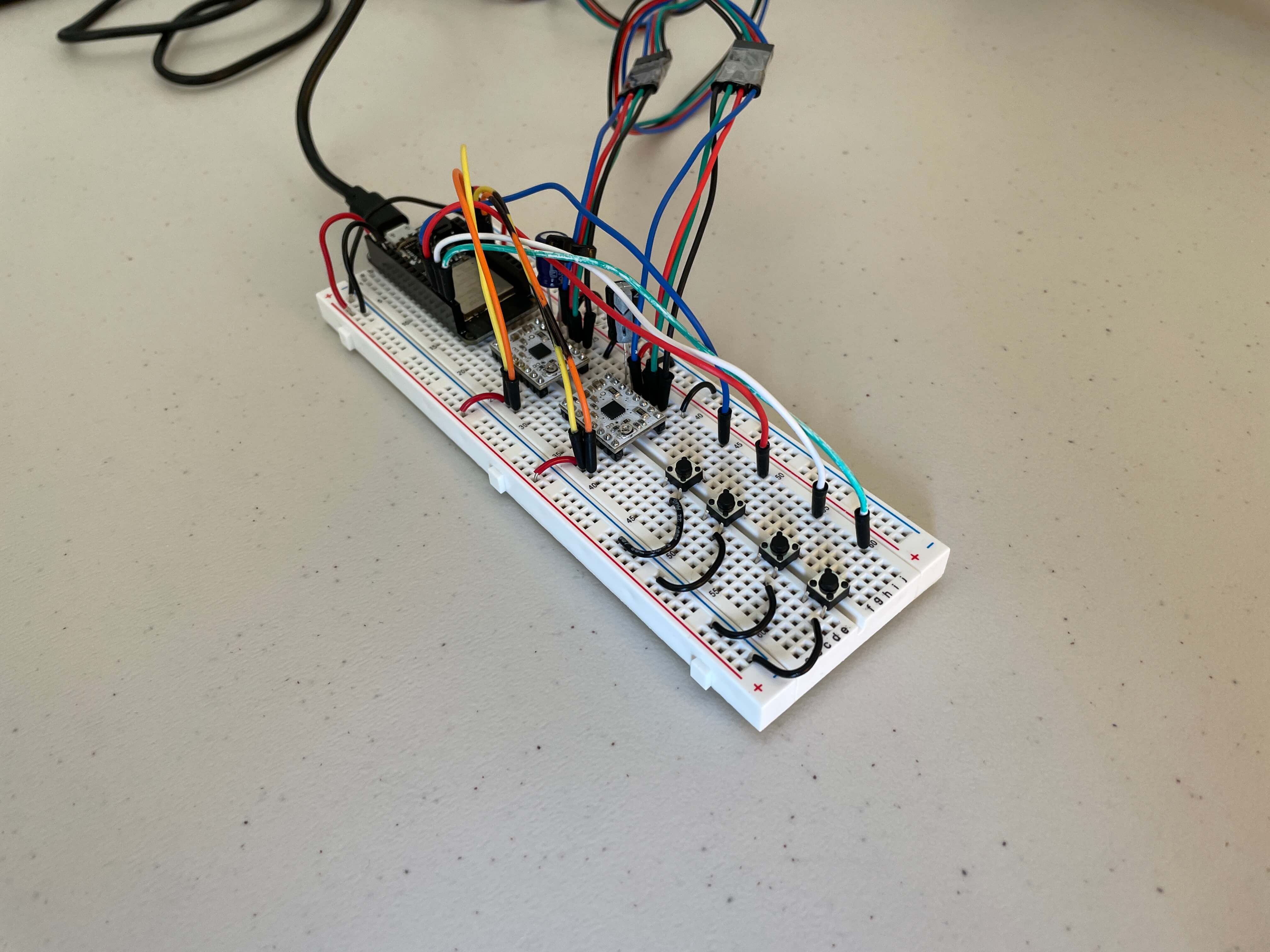
The pictures below are of the random movement machine. The image of the wiring is what one DRV8834 Low-Voltage Stepper Motor Driver needs. All of the other machines use the same drivers and wiring for the drivers as this one.
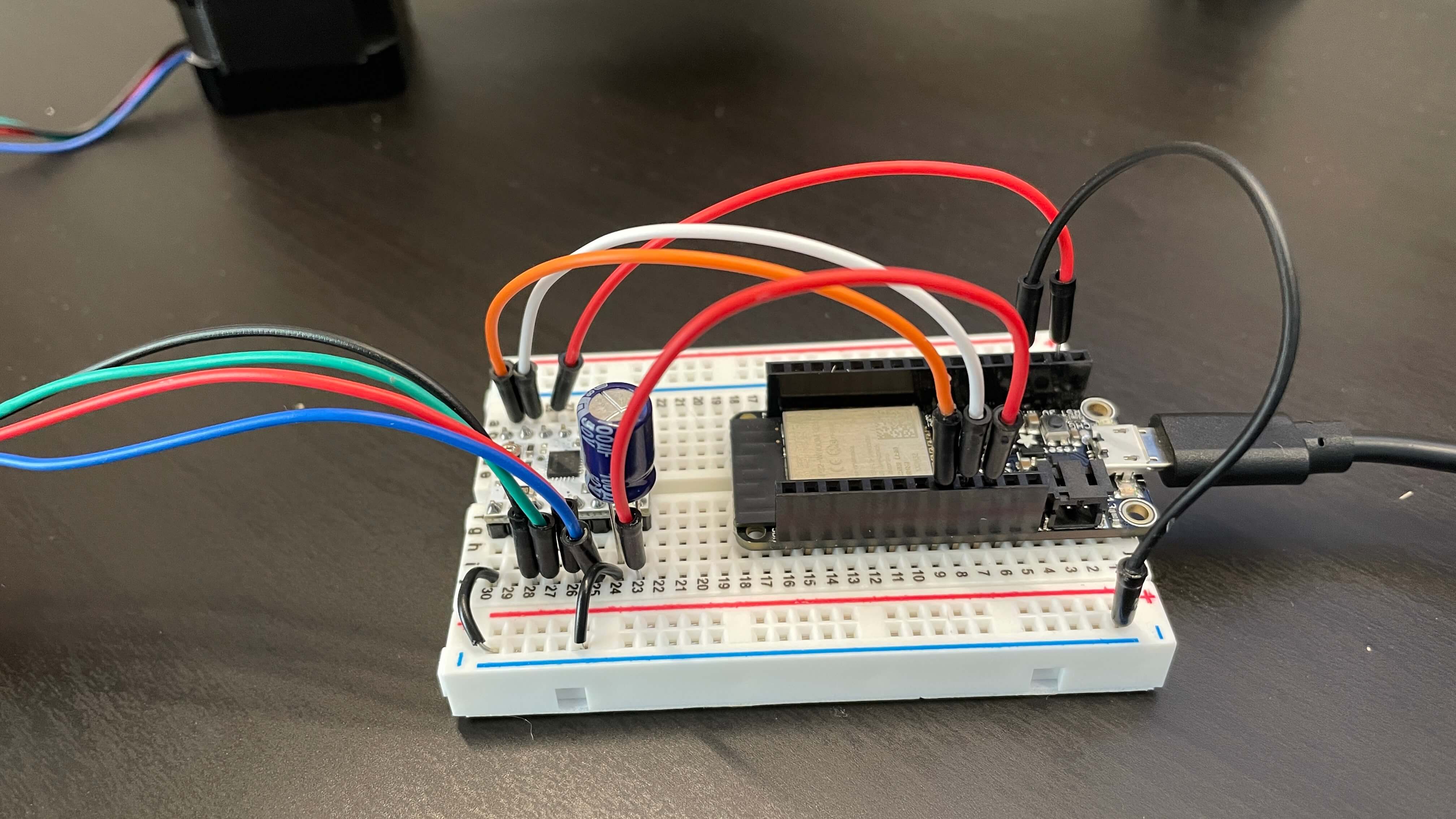
On the Arduino embed to the left, there are two tabs. The first one is for random stepper movements and the second is for controlling the stepper using two buttons. I'll start by talking about the random movement machine.
The random movement machine uses the AccelStepper library. To start off, I inluded the AccelStepper library at the top. Then I defined the step and direction pins for the motor. These two pins are needed for the stepper driver we are using. After that, I defined the stepper motor using AccelStepper. There is no setup because this is just a very basic example.
The first if() statement is basically saying "if the stepper motor is being told to move, then do this..." Inside the if() statement are three stepper movement functions. The stepper.moveTo() function is for setting a distance to move to (either positive or negative); the stepper.setMaxSpeed() function is for setting the maximum speed in steps/second that the motor spins; and stepper.setAcceleration() function is for setting the acceleration rate of the motor. And finally, the stepper.run() function executes the commands above using the stepper movement paramater functions given.
A video for the random movement example machine is below.
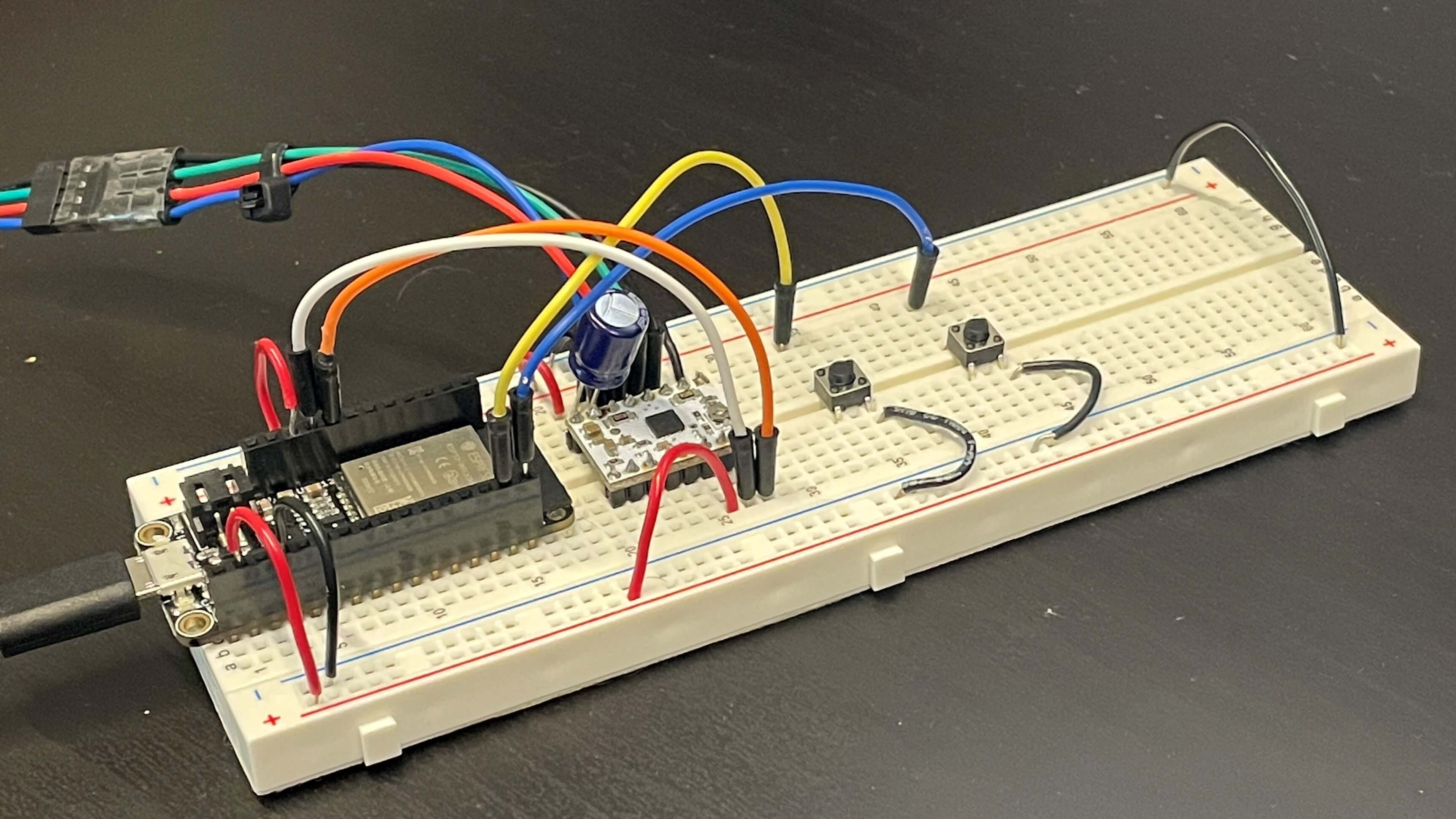
The second tab code is for controlling the movement of the stepper motor only using digitalWrite() functions. It doesn't use the AccelStepper lirbary, so the functionality of the stepper motor is limited to just step movements, no acceleration. The way it works is just by repeating the digitalWrite() function every one milisecond with either HIGH or LOW as the output. I change the direction of the motor by using digitalWrite() with the direction pin as an output of either HIGH (motor turns counter-clockwise) or LOW (motor turns clockwise). And that's pretty much all that was.
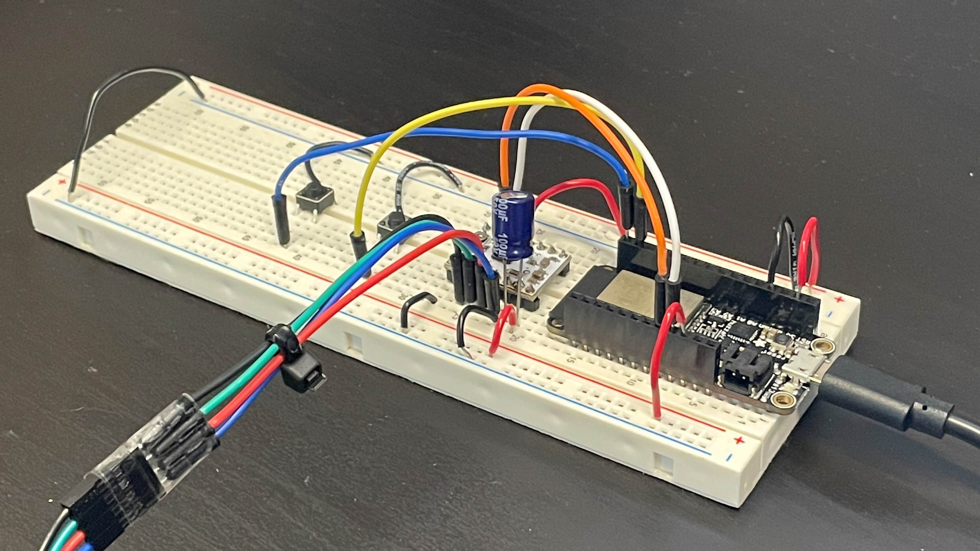
I didn't include a video of how it works (because I further improve on this example later), but I did add pictures of my breadboard with the two buttons below.
Single Axis Button Stepper Control
Without using the AccelStepper library, you are pretty limited on what functions you can execute with your stepper motor. So, I decided that I would learn how to use the AccelStepper library for my next machines. It worked out much better than I thought. I stumbled across a few problems, but I also figured out ways to fix those problems, all of which I documented below.
One thing to note is that I used the exact same wiring as I did in the example above. So, those pictures above show exactly what the breadboard circuit for this code looks like (because it's the same).
Also, another thing to note, I write a lot of my though process and what the functions do in the code itself. This can be seen with the double-hash lines and pseudo code, again, both in the code itself.
I used what I learned from controlling the motor without the AccelStepper library and my newly learned basic knowledge on the AccelStepper library to control the stepper motor on one axis.
I start off by doing the normal stuff: including the AccelStepper librariy, defining motor pins, defining button pins, and defining the stepper motor itself. I also included a milisecond timer with a one second interval for the serial monitor (I talk about that later).
At the end of the setup part, there is code for "homing" the axis. I put "quotes" around homing because it's not really a good way of doing it at all. The motor spins for 2500 steps, which I calculated was a bit more than the total amount of steps actually needed for the carriage to travel from one end to the other. Essentially what happens is that the carriage is guaranteed to hit the left side (the side I have it set to) because the step amount I wrote for the motor to move is larger than the range of the carriage movement itself. If the carriage hits the left side before the motor finishes turning, the whole thing explodes. No I'm kidding. That doesn't happen. In fact, nothing happens. The motor can't turn because the carriage can't move, so it works out pretty well actually.
The movement works in that each time a button is pressed, the motor turns in 300 step segments either clockwise or counterclockwise. I used 300 steps because I found it to be a good distance and it worked well with my other numbers I talk about later. But, one problem was that there were no limits to the movement, meaning if the carriage was on the right edge and the right button was pressed, then the motor would keep trying to turn and cause problems. A video of this can be seen below.
So, I created an Xpos variable that changes depending on which button is pressed. If the right button is pressed moving the carriage rightwards, Xpos is incremented by +1, and when the carriage is moved leftwards Xpos is incremented by -1. I use this to determine the minimum and maximum position that the carriage can be in.
I created 9 total positions with 8 segments in between that the carriage can be in (i.e. 0/8, 3/8, 8/8, etc). The motor turns in 300 step segments, so the total length of the 8 segments is 2400 steps, which is less than the maximum because I don't want the carriage to bump into the other side while using buttons. I then added if() statements to both buttons that basically say "if the carriage has reached either limit, don't allow another button press moving towards that limit." A video of this is seen below.
In tandem with the "homing" system, the position system worked very well, as now, the machine would home and declare it's position by itself. But, this led to another problem. Firstly, I created some Serial.print lines of code to output the exact position (out of 8) and exact step position so I could easily see what the position of the carriage was. That wasn't the problem but rather helped me solve the problem.
The problem was that if the carriage was at a limit, and the button was pressed, although the carriage itself didn't move, the Xpos changed. Now this caused many issues because it would cause the position to be some whacky number, and because I have my button movements based on the Xpos variable, the movement of the carriage would be disrupted.
To fix this, I added in the last two if() statements that basically say "if the carriage is all the way to the right (or left) and the right (or left) button is pressed, then set the X position back to 8 (or 0 if at the left)".
The problem visualized and solution are shown below.
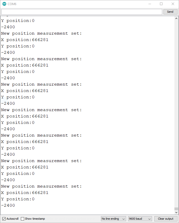
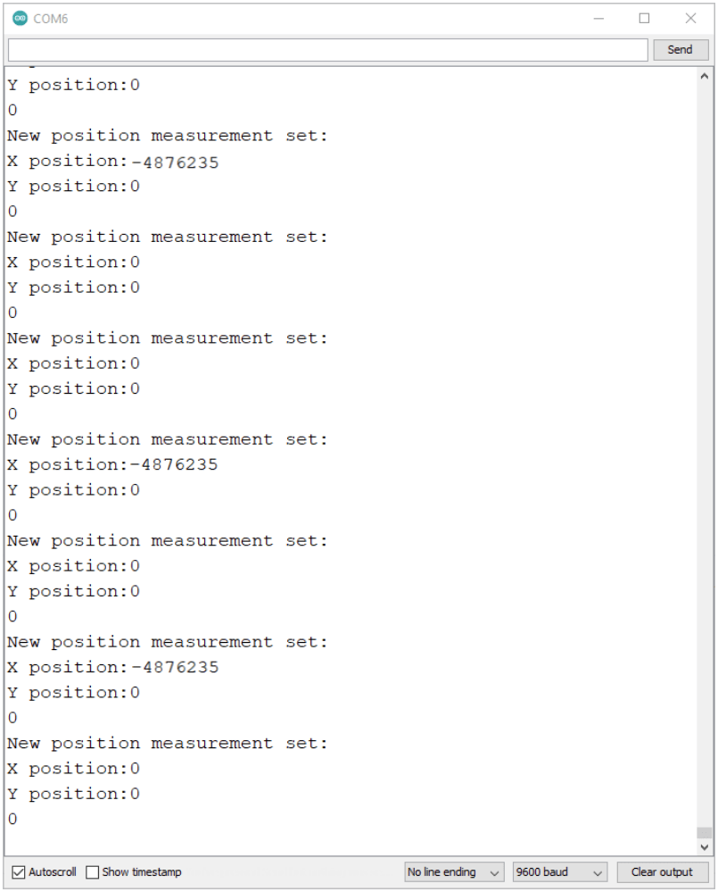
This solved all positional issues. The first image above shows the erroneus positional readings, and the picture on the right shows the position reseting to the minimum X position of 0. Now, I was able to finally improve on this design by adding in the Z-axis.
Double Axis Button Stepper Control
Because I already had all the code written for one axis, I was able to easily add in another axis without too much trouble. The bulk of the changes were just adding variables for the new Z-axis and chaning old variables to X specific ones so I could make new Z-specific vairables. I also had to make a new axis and carriage using the rest of the lazer-cut pieces. The process for creating and attaching the new axis is shown below.
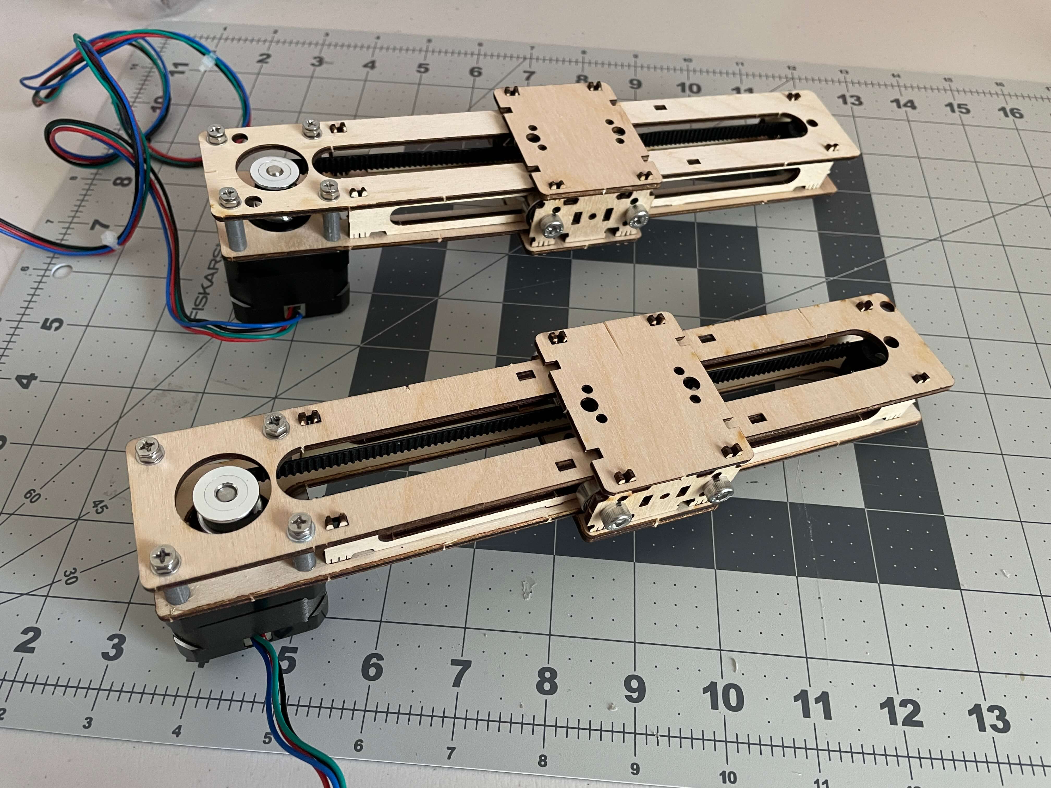
I created the second axis and oriented the motor wires to left side. I changed the motor oreintation on the old X axis to do the same. This was so the Z-axis motor wires can have more space to flex instead of being pressed against the X carriage.
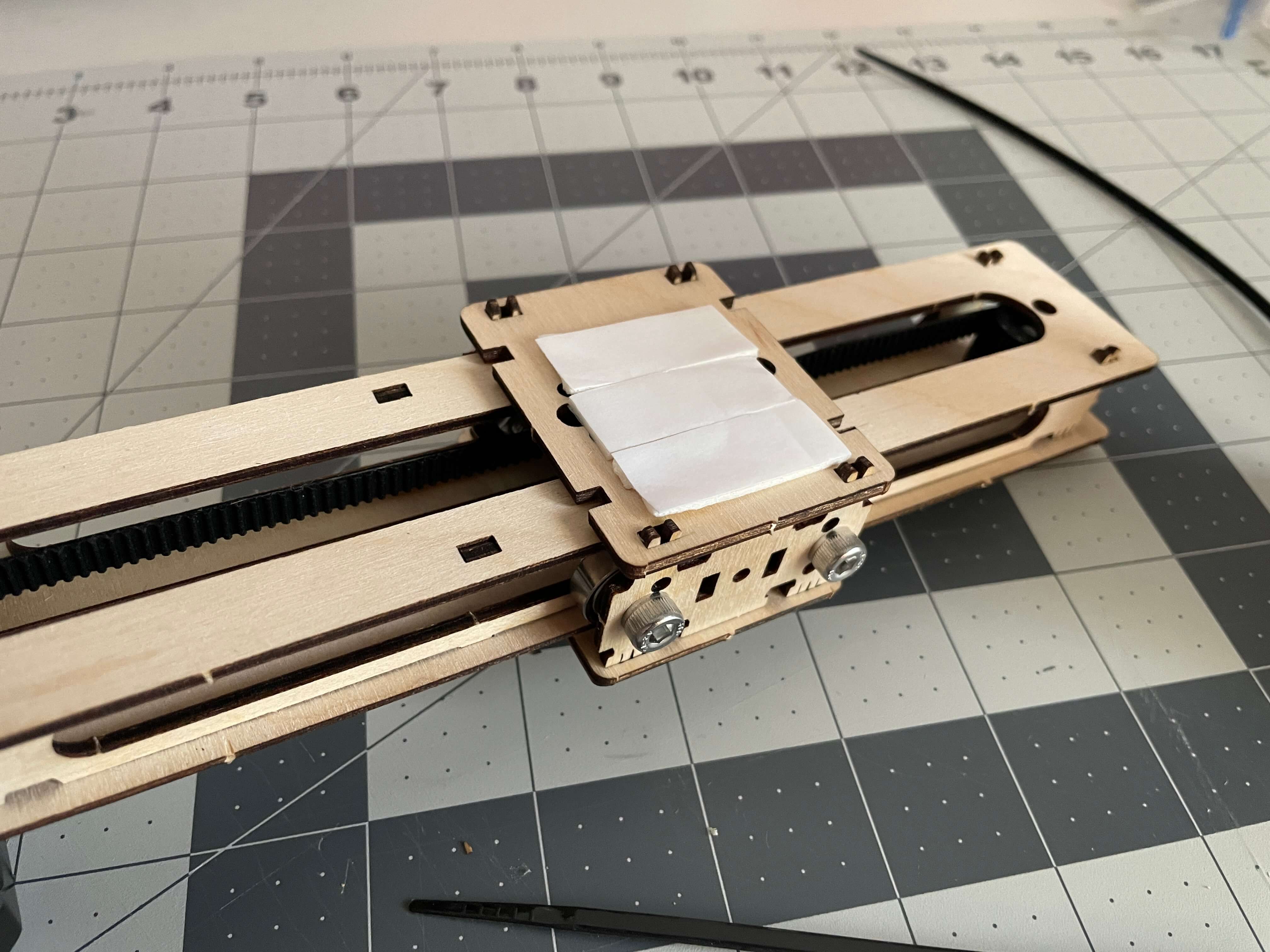
To attach the two axis, I just used some double-sided tape, which turned out to create a really good bond as seen on the gif to the right.
There are many ways to attach the two axes, but at this point, I still hadn't decided where I was going with this assignment, so I figured a temporary solution with double-sided tape would to the trick.
Now, it was time for the coding part. Like I said, the coding part was pretty easy because I just had to duplicate and edit the code I already had for the X-axis.
Again, because the code is very similar to the code of the last machine, I will just breifly go over the changes here.
I included the MultiStepper library, which is part of the AccelStepper library, but since I'm not exactly sure if some functions I used were part of the MultiStepper library, I just kept it in.
I then defined integers to each motor pin and button pin for the Z-axis. I created a new variable for the Z position, Zpos, which is used for setting limits of the Z carriage.
I redefined the regular stepper to StepperX and StepperZ. This allows me to indivudally control each motor. I changed all the old regular stepper. function beginnings to stepperX. so that they would control the X-axis.
I setup the Z stepper parameters (maximum speed and acceleration) added a Z-axis homing part to the homing section of the code. Then, I basically duplicated the X-axis while() functions and changed the stepper variable to StepperZ for the Z-axis.
Finally, I added the Serial.print lines of code for the Z position and added the Z maximum and limit reset with the very last two if() statements.
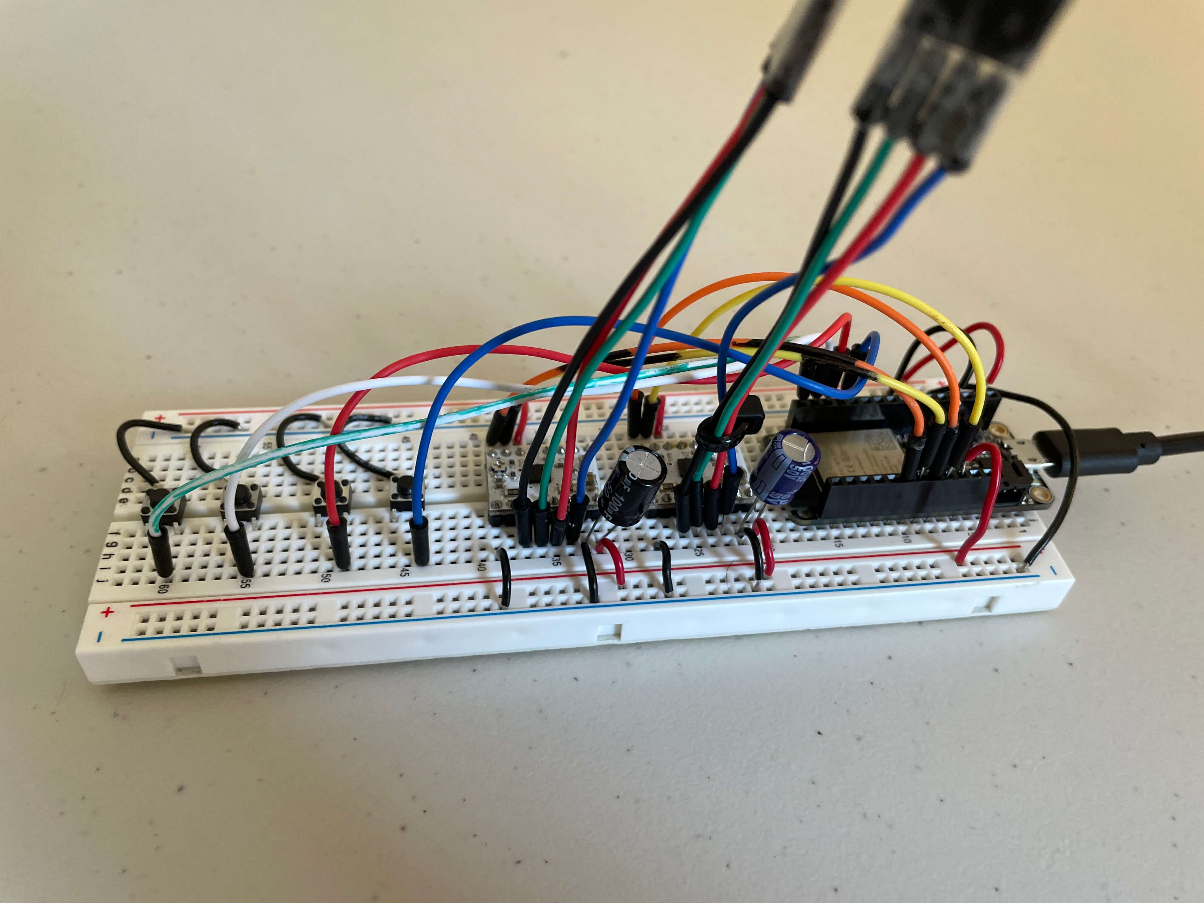
Now, the Z-axis functions exactly the same as the X-axis does and is controllable using two more buttons. This increased the total buttons on the breadboard from two to four. I also had to add another stepper driver to the circuit, which added a lot of wires. The circuit pictures are further below.
That's pretty much all there was to adding the Z-axis: add new variables, change old variables, and add new Z-axis functions. A video showing how it works is embeded below.
Below are the images of the breadboard circuit. It's pretty much double the wires of the single axis machine. I color-coded the wires and labeled which color corresponds to which pin in the code.
Now that I had two axes working perfetly, I figured out where I wanted to take this assignment. I wanted to make a fruit/vegetable chopping bot.
Button Controlled Fruit and Vegetable Chop Bot
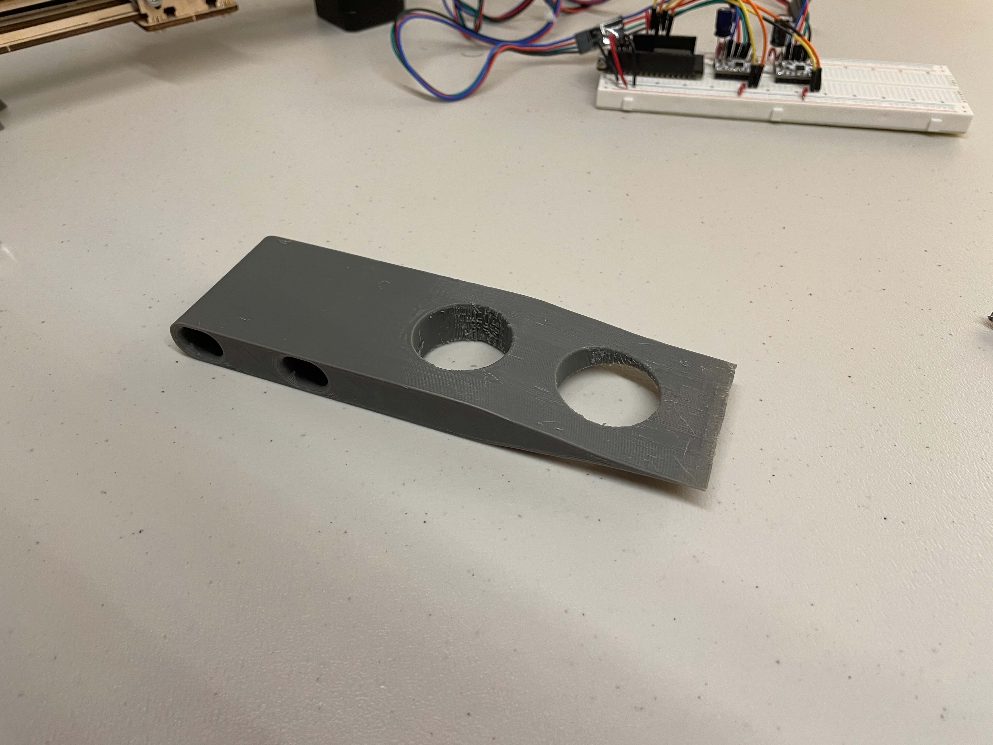
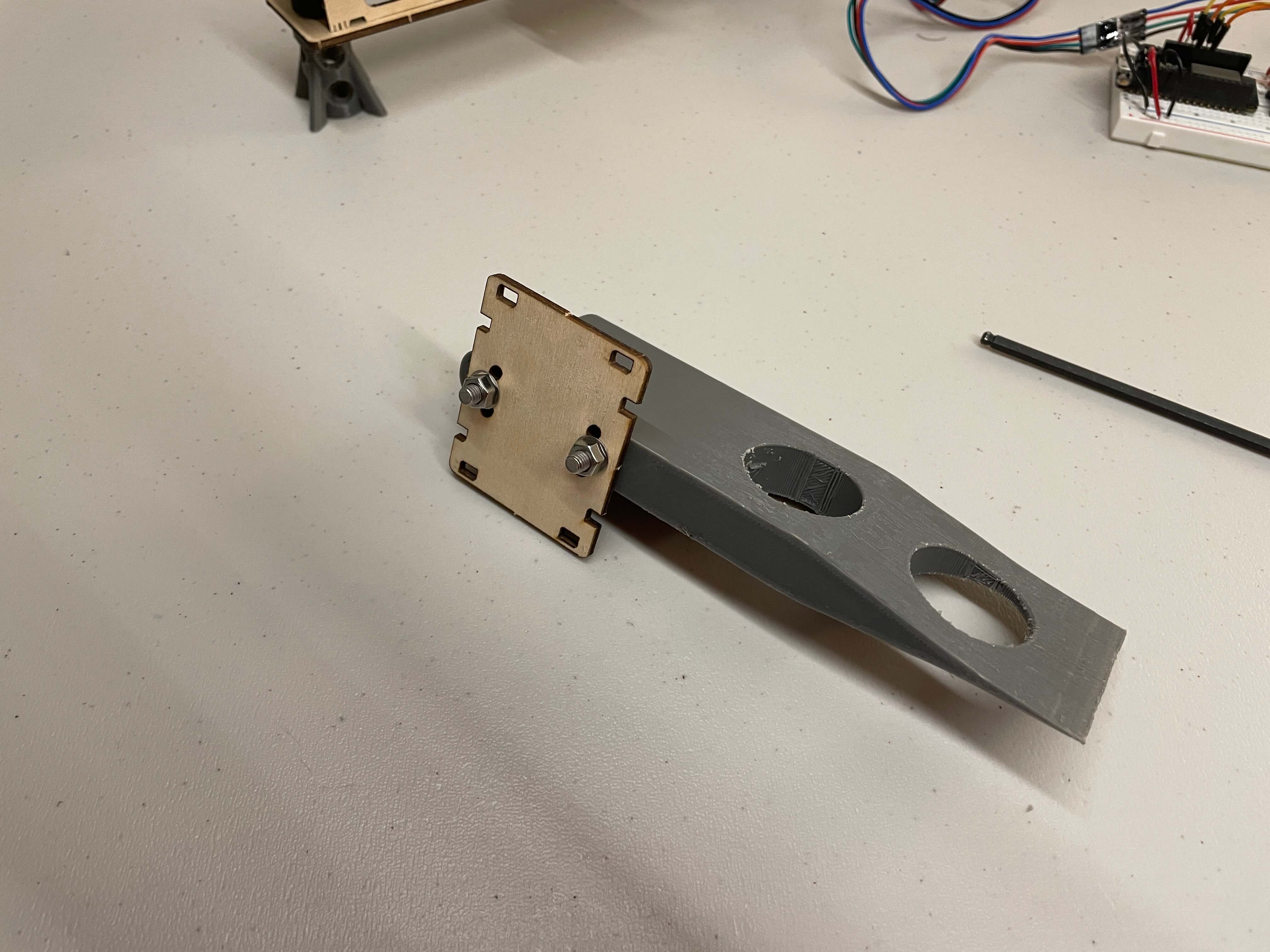
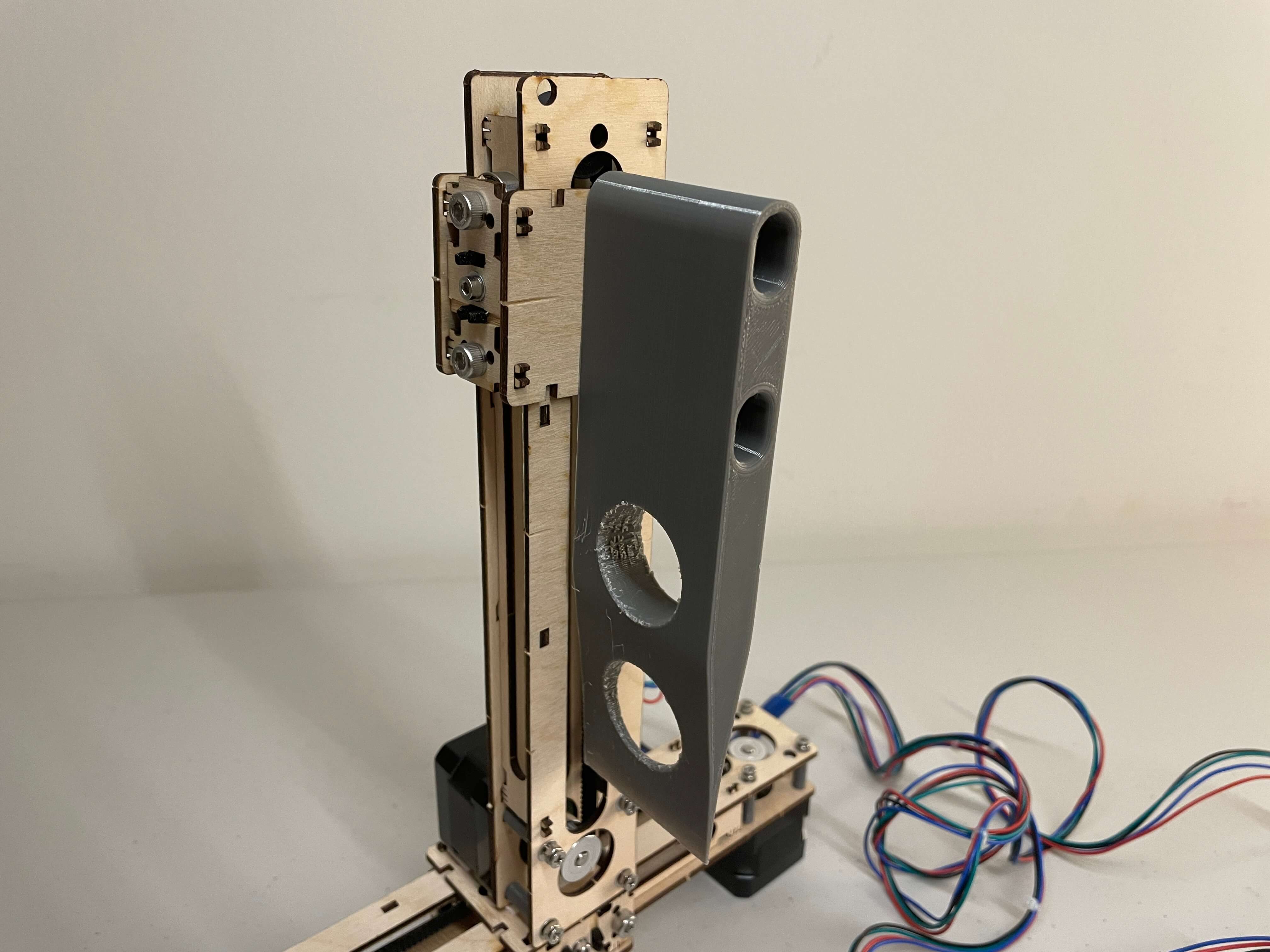
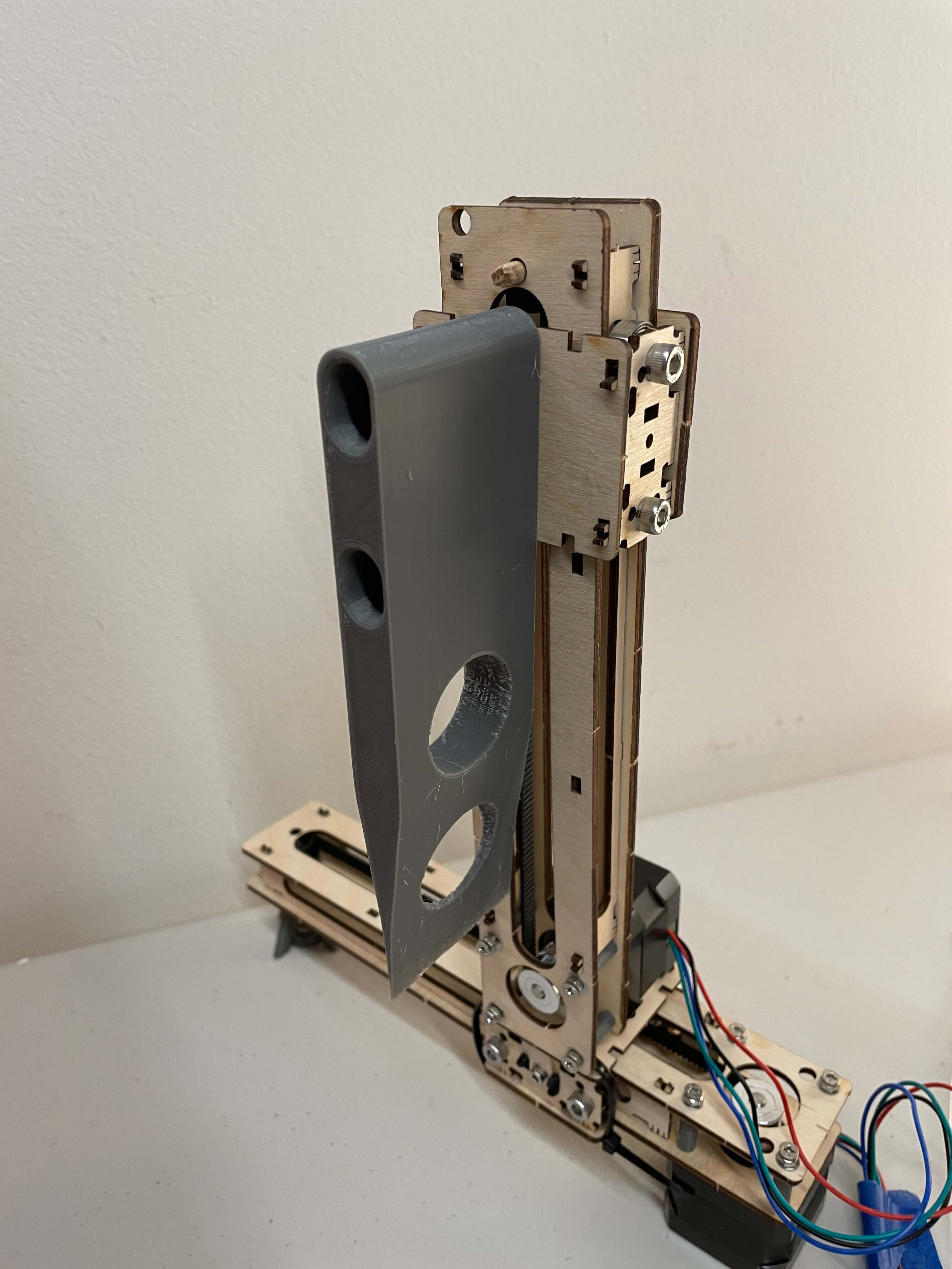
For my chop bot, I 3D modeled and printed out a knife, which isn't sharp at all, and changed some of the code around. I designed the knife to perfectly match the height of the Z-carriage and attach to the front face piece using the two included m5 screws. I made the screw holes on the knife a pill shape, rather than a circular shape, so the knife height can be slightly adjusted up or down, depending on the thickness of the double-sided tape. I also cut out two holes near the bottom for saving material and because it looks cool.
It now looks more like a fruit and vegetable guillotine than anything else.
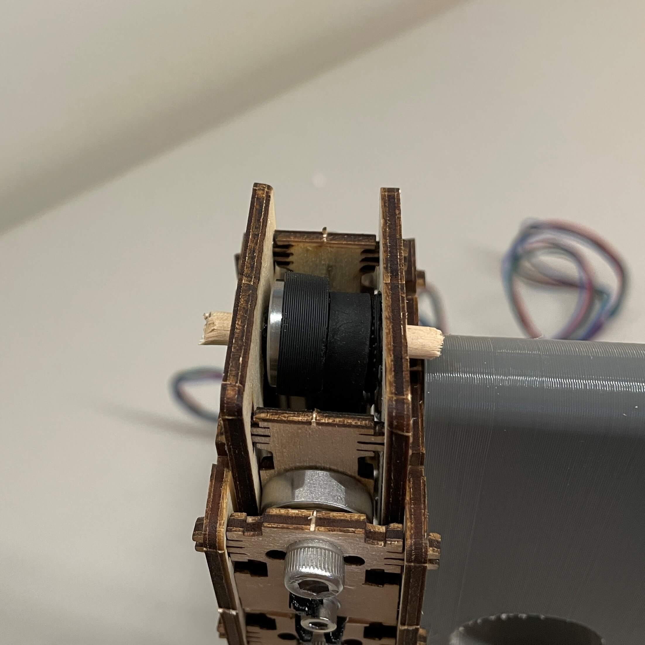
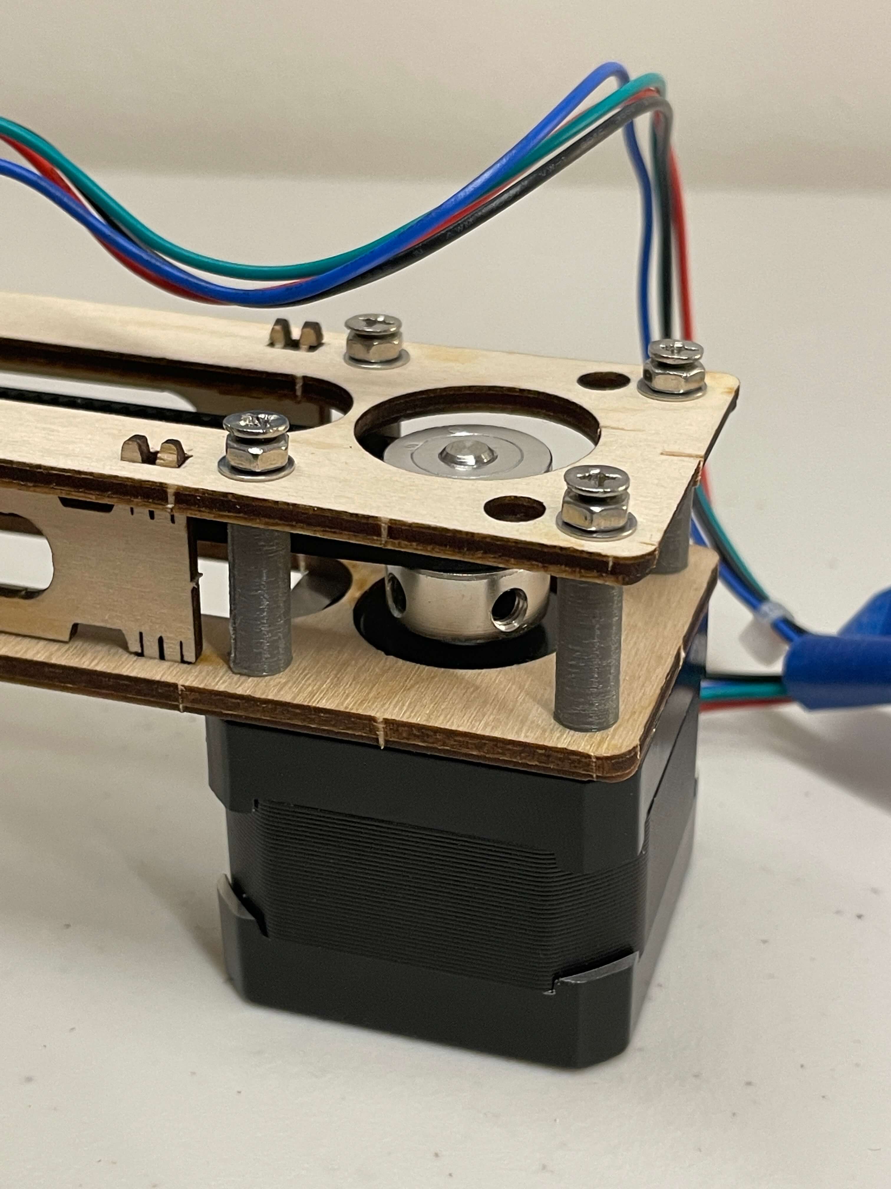
One physical change I made was a modification to the Z-axis pulley screw. Because the Z carriage kept getting a lot of friction on the Z-axis causing step skips, I replaced the M5 screw that attaches black timing belt pulley to the top of the frame with a wodden dowel that was about as equally thick as the M5 screw. This solved the friction issue because now the belt was perfectly straight, as was the pully itself. The dowel runs through both sides of the axis. This is shown below
The biggest changes in general for the Chop Bot are the removal of one button and changing the Z movement to go all the way down and then back up. I removed one button because I only wanted one "chop" button. So you can move it left, right, and then chop, which is the down and up movement combined. This actually meant that the code got smaller because I removed quite a bit. There is no code for the 4th button and Zpos variable anymore. A demonstration of this is shown in the gif below.
Another thing I changed was the Z range. I made it 2450 instead of 2400. This is so the knife goes all the way to the ground and back up. The old 2400 range was just so the Z and X carriages don't collide into the sides. I found that 2450 was the perfect amount, especially with the small adjustments on the knife itself.
Since I finally got all the functions working for a chop bot, I needed to control it using the computer or my phone to fulfil the assignment requirement. I show what I did in the next section.
Arduino IoT Controlled Fruit and Vegetable Chop Bot
To control my chop bot using a device, I decided to control it with Arduino IoT Cloud. Because I have already shown how to set up Arduino IoT Cloud in my last assignment page, I won't go into as much detail as I did during that assignment here.
Just to reiderate from last assignment, Arduino IoT Cloud is a platform where you can control devices using a network connection using widgets on a dashboard. You create global variables for a "thing," as it's called, which then automatically writes in the code. All I had to do was edit the code by adding in the button functions. And, Arduino IoT Cloud works from anywhere around the world, so as long as you have an internet connection, you can control a microcontroller with a WiFi conneciton, in my case, it's my Huzzah Feather with the ESP32 microcontroller.
The three global variables I created were leftButton, rightButton, and chopButton. These variables are basically the same as the button functions from the last machine, where each button produced a function. Other than that, I just transferred all the code from the last machine to this one, so it was really simple to set up. That's why I did all those button prototypes first, so putting it all together on Arduino IoT would be easy.
Below, I embeded videos of all my testing using the fruit/vegetable chop bot.
This first video shows my Arduino IoT dashboard for the chop bot with three pushbutton widgets.
Of course, no knife test would be complete without a hand test. Unfortunately, the motor doesn't have enough power to actually cut through most fruits and vegetables, which is shown later, and therefore my hand was not cut.
I then commenced the live fruit tests. They weren't very successful, but, they were fun to do. I count that as a win. This first one is a long watermelon piece cut test. The biggest problem is displayed of the lack of weight, causing the whole machine to tilt.
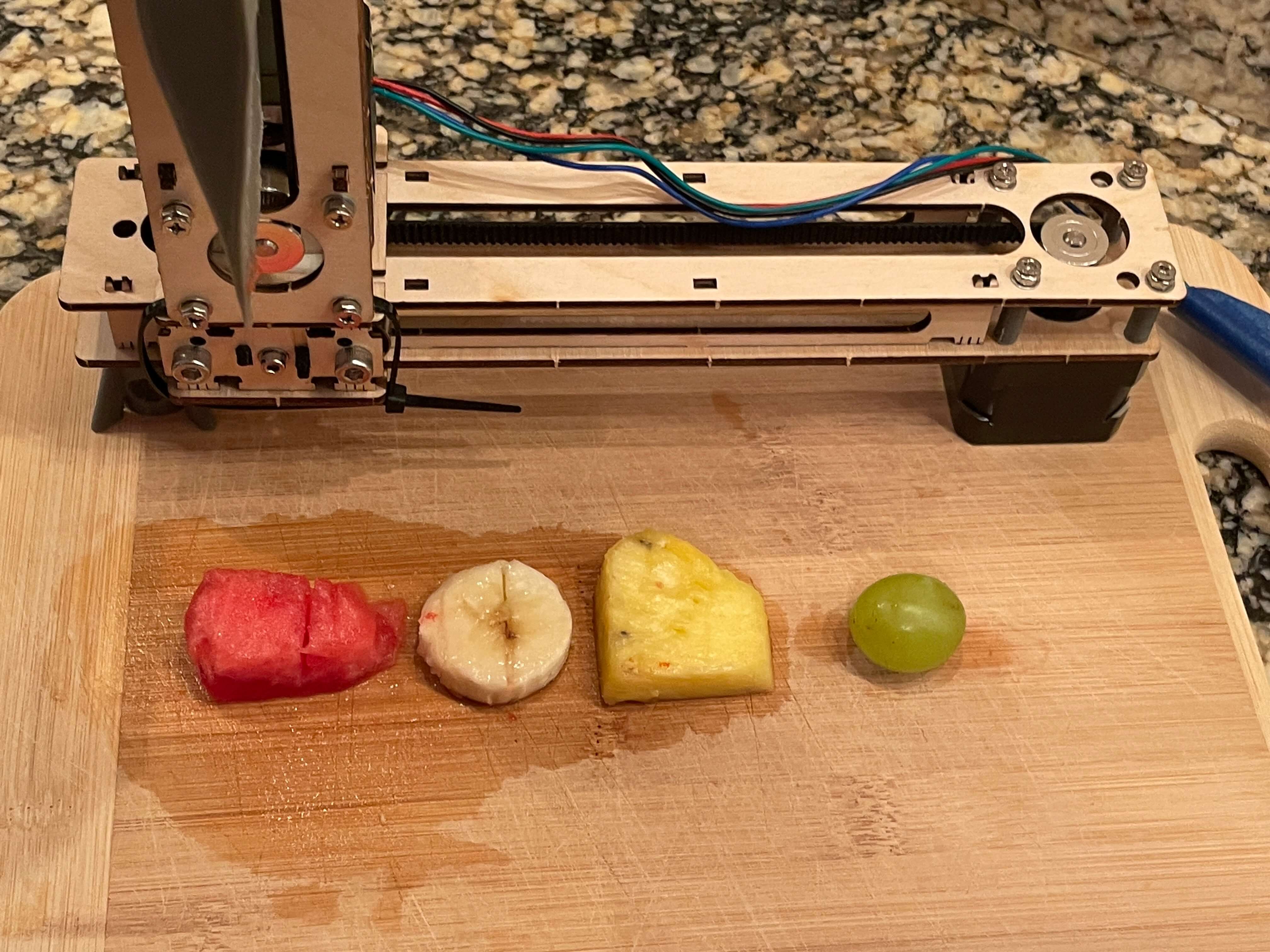
The next test is with a variety of fruits. It worked kind of well with the watermelon and banana pieces but didn't work very well with the pineapple and grape. It makes sense because the pineapple and grape skin are more dense than the banana and watermelon.
Because I saw that the whole chopper was tipping when the knife went down, I put my hand on top as a weight to counter the tip. It definitely worked a lot better than it did without a weight, but it still didn't fully cut through the fruits. That's probably just because the blade is a bit too high, otherwise I think it would've cut through the watermelon and banana pieces.
Finally, after all the testing was over, all that was left the aftermath of the fruits. This is shown in the image below. The watermelon and banana slices had a solid cut through them, but the pineapple slice and grape were left unharmed.
3D Printed Parts
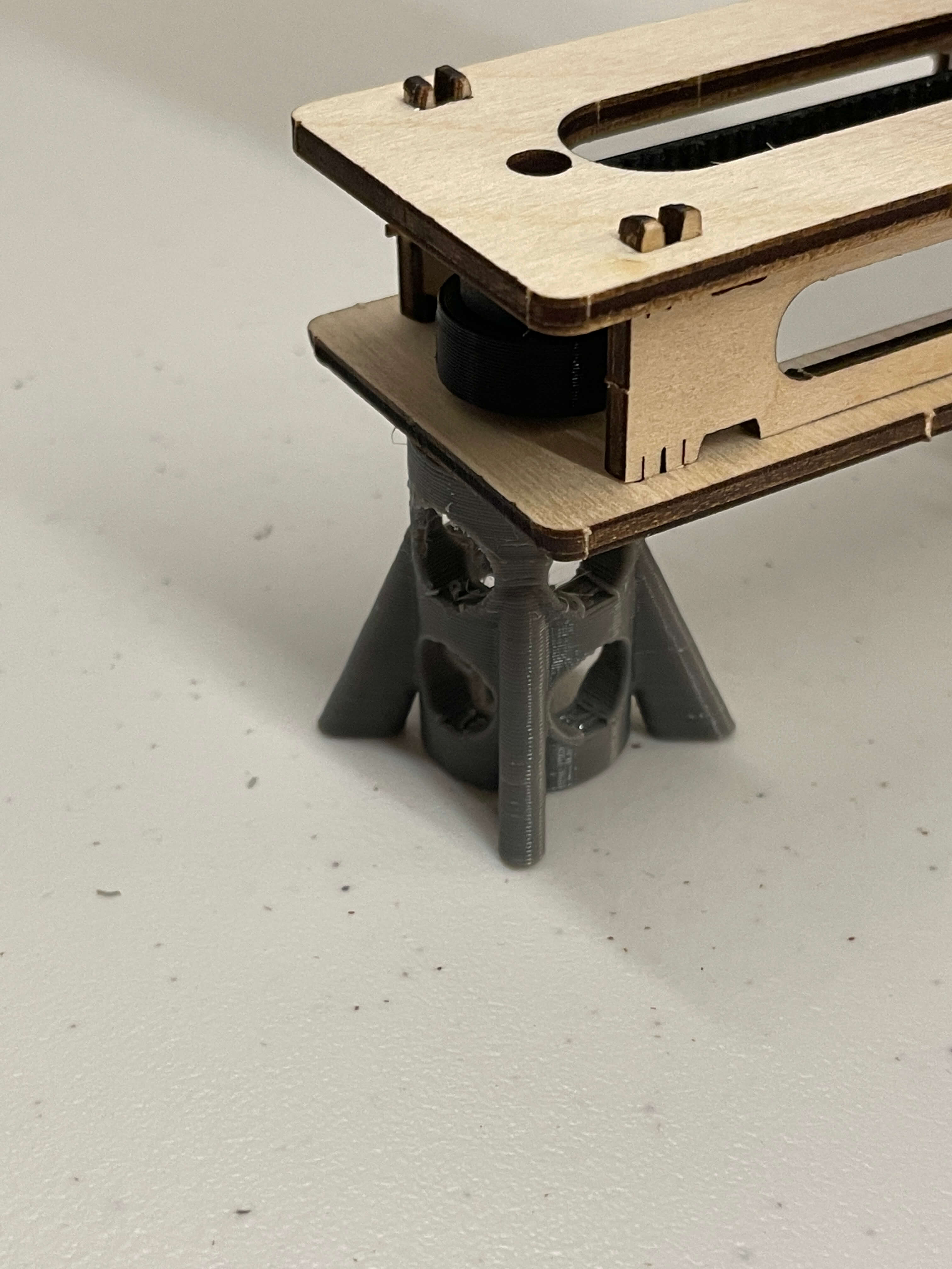
I designed and 3D printed three parts: the laser-cut assembly spacer, the X axis leg, and the knife itself. I printed 8 spacers total (4 per axis), one X-axis leg, and one knife piece. Below are pictures of the parts and their respective F3D downloadable file links.
What I Learned
» How to use many of functions in the AccelStepper Arduino library
» How to use some functions in the MultiStepper library
» How to create a virtual positioning field
» Ways to creatively set limits
» Ways to creatively home stepper motors