What To Do
1a. Program a microcontroller to produce an output using at least one button for input.
1b. Include a conditional statement and a for() loop.
2. Start working on the 3D design for the final project.
What I Did
For this assignment, I made a mini light show. I used the Metro board, the long breadboard, and Arduino IDE. I used the conditional statements that we learned in class, like if() statements and for() loops, to control all 5 of the LEDs in various ways. Using both of these newly learned aspects of coding on Arduino, I was able to program 5 buttons to control 5 lights. In total, I'd say it took me around 4 to 5 hours to finish all of the electronics building and programming, which I think is really quick considering I had to learn and apply the different fucntions we learned into my light show.
The final product turned out great, especially in the dark. Now that I have the code written and saved and have a better understanding of making circuits with multiple LEDs, I feel in the future, I can make much more intracate LED "shows" and other interactive LED circuits.
To the right is a gif of my favorite moment of one of the "shows." Technically, there are two pre-made "shows". The buttons on the back left and back right are for the shows and the front three are for manual control.
My orignal idea for this assignment was to only have the 3 front buttons but to have multiple functions for the buttons to essentialy make a manual light show. I still went with this idea, so the three buttons in the front do manually control the lights, but I ran into many issues when controlling different lights with the same buttons, which I talk about later.
Below, there are two embeded videos of demos of my circuit in the light and the dark. Like I said, all the buttons have some functionality, and the 3 bottom buttons are for manual control, which will be shown in both videos. I talk about my programming and build process further down the page, as I talk about the class demo circuits first.
In all of the demo cricuits, I used a 470 Ohm resistor for the LED(s). Although, I don't really know if I needed them because I was using the one on the Metro board. For the final light show circuit, I used 100 Ohm resistors on all LEDs to keep it simple.
For references, I used the Arduino Language Reference page, as it was very helpful for searching up specifics about various variables and functions. Learning about the functionality of for() loops was challenging because we jumped straight into using for() loop, skipping the while() loop. The for() loop is essentially just a shorter version of a while() loop. I learned how to use the while() and for() loops by watching these videos I embeded below.
Two Button LED Circuit
This lab example is one that I heavily referenced for my light show circuit, as mine uses 5 buttons, 3 of which sharing similar functionality to the buttons in this circuit. This circuit was the first time I used push buttons and the built-in pullup resistors.
One thing we learned in class what the difference between pullup and pulldown resistors are. Our Metro boards have built-in pullup resistors, which essentially just inverts the reading of an input. So, in my sketch, both buttons have to be pushed down to be in a LOW state. Now, this is only possible since I used pullup resistors or else any button press outputs as HIGH, not LOW.
In the gif below, the red LED only turns on when both buttons are pressed. The coding for this was very helpful for my light show, as two of the LEDs and three buttons on my circuit have the same functionality as the red LED and two buttons on this circuit.
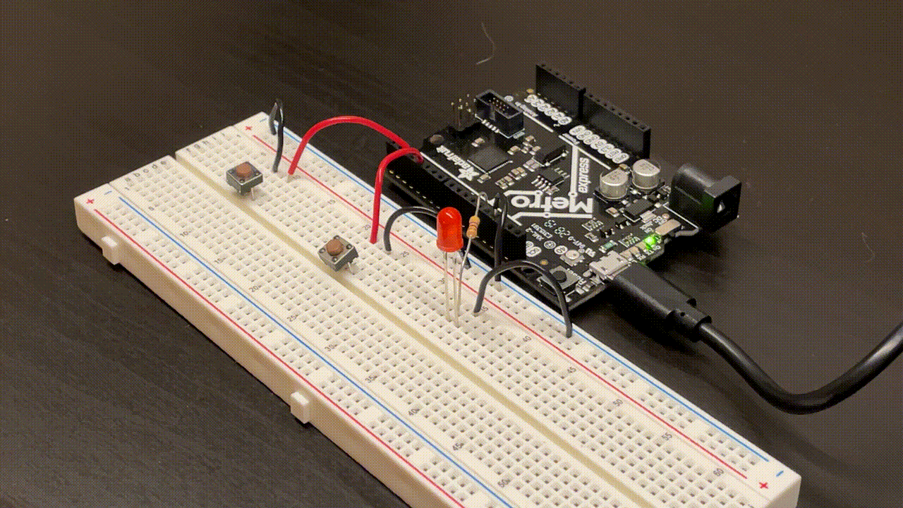
This was also my first time using logical operators, symbols that can be used in expressions to combine two or more relational expressions. I used &&, which means "and." So, in this sketch, the if() statement says that "if the left button and right button are both both in the same state, and the left one is in a LOW (meaning both are in a LOW state), then the red LED turns on." The if() statement was a bit confusing to understand at first, but I soon got a better understanding of it during the lab and when I started to make my own circuit.
Nested For() Loop Circuit
Although I got the hang of reglar for() loops in circuits, I'm still a bit iffy on nested for loops. However, the example we did in the lab helped my understanding of the application of nested for loops.
The function of the code is pretty simple: one LED toggles on and off every second and the other toggles every minute. In this example, we used regular int variables as well as bool variables. In the gif below, the blue LED is toggling every one second while the yellow LED is staying on (the gif is repeating so the yellow LED never turns off).
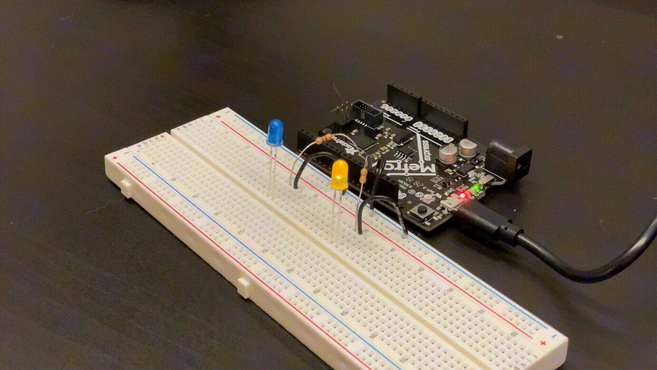
This was my first time using the bool variable, and I can see how it's useful for storing small bits of data. It can only store two values: true or false (in my case, on or off).
This was my second time using logical operators. In this example, the "!" operator is used, which means to execute the opposite. Specifically, it is used to change the states of the LEDs from an on or off state to a not on (off) or not off (on) state.
Button Dimming LED Circuit
This circuit was the last of the 3 main demos we did in class and lab. In this example, we used a button to control an LED, which runs on a for() loop.
I also referenced this example a lot when making my final light show. What's happening is that the button press activated the LED, which then dims over a period of around 4-5 seconds. The gif below shows the circuit.
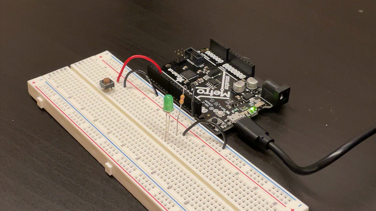
The way to adjust the LED dimming time is by increasing the delay. I have the delay set to 10 miliseconds, but if increased, then it will take longer to finish the for() loop.
Another thing I could've done was to decrease the increment of the int "i" (assuming "i" is greater than 1). However, because the increment I already have set is -1, I am using the lowest increment I can actually use (because the variable "i" can't be a fraction of 1).
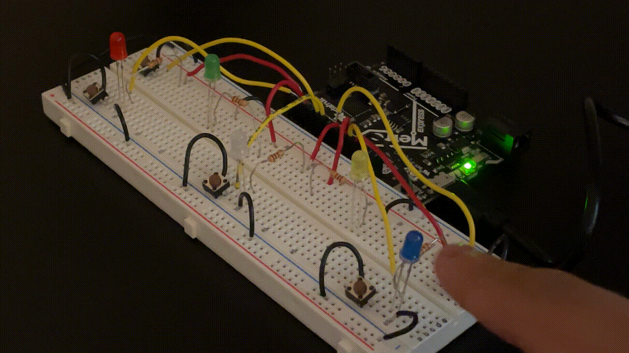
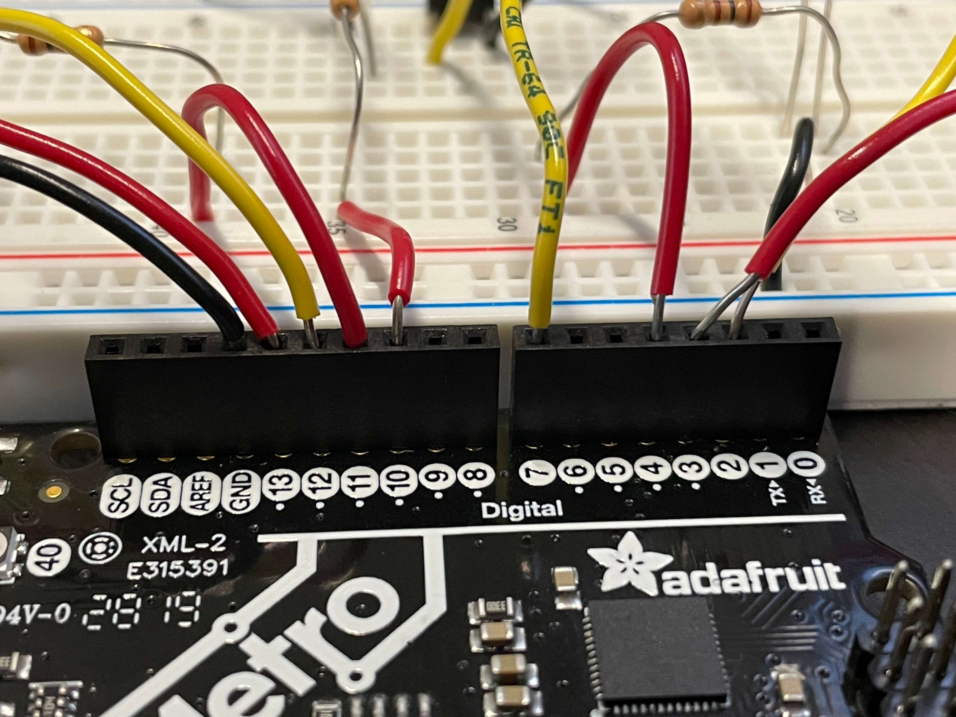
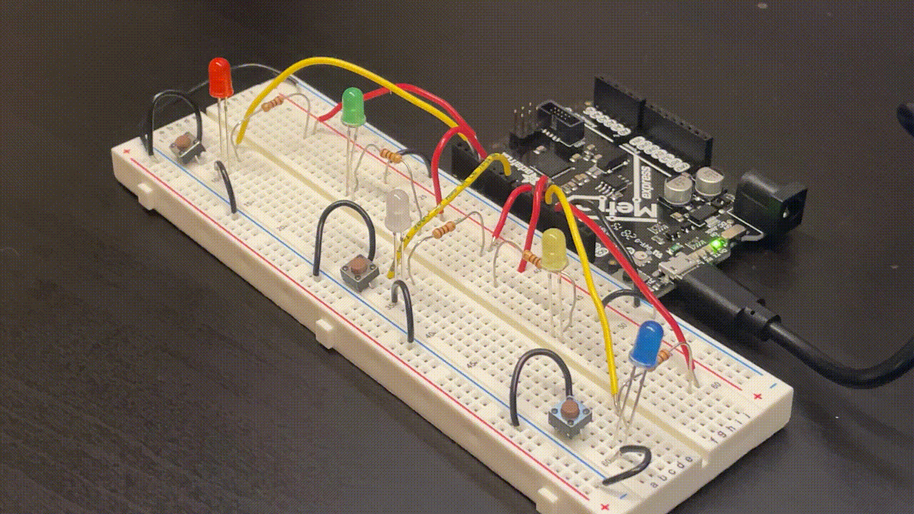
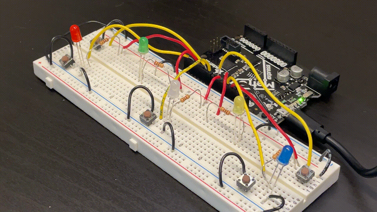
Light Show Circuit V1
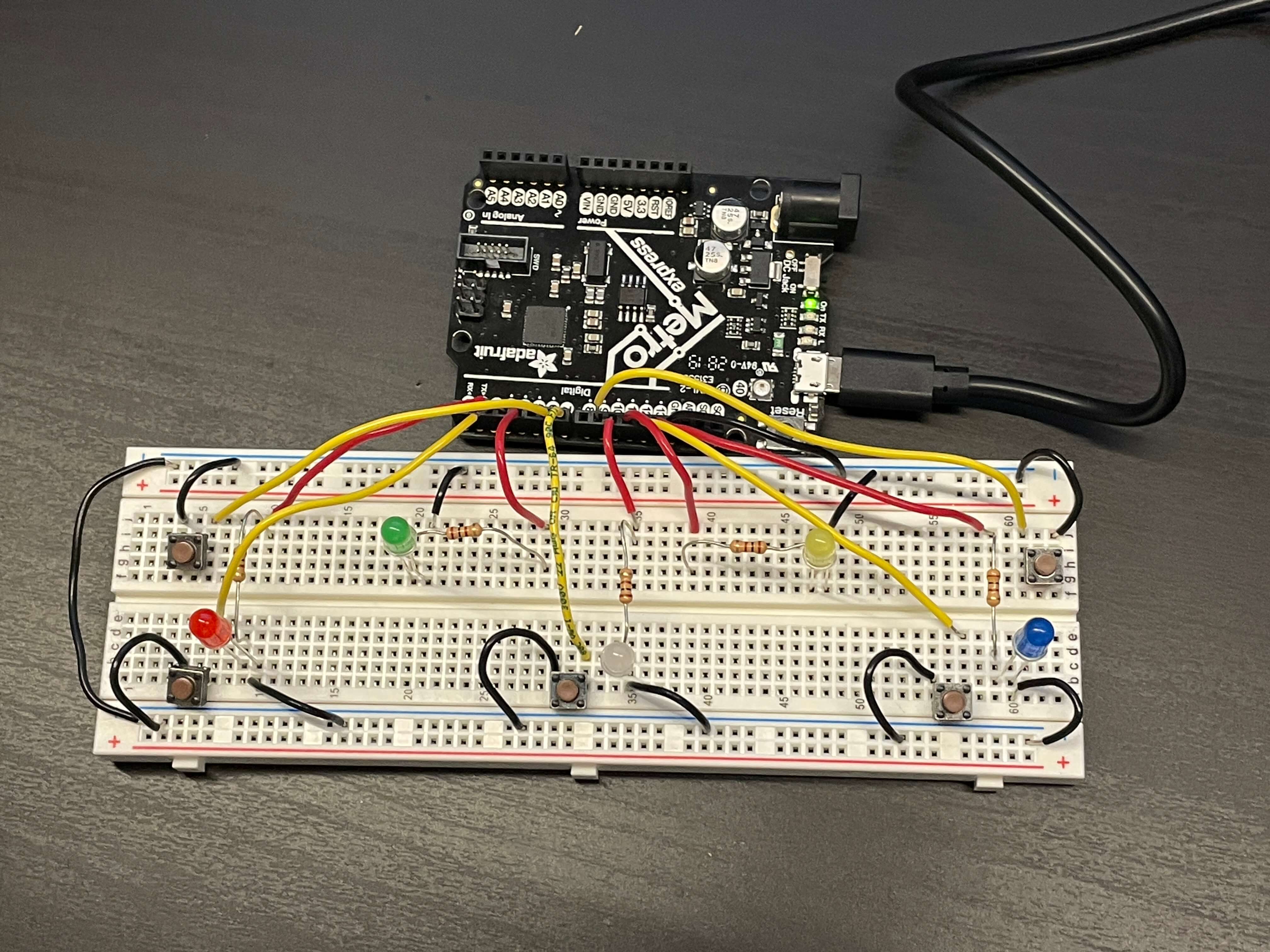
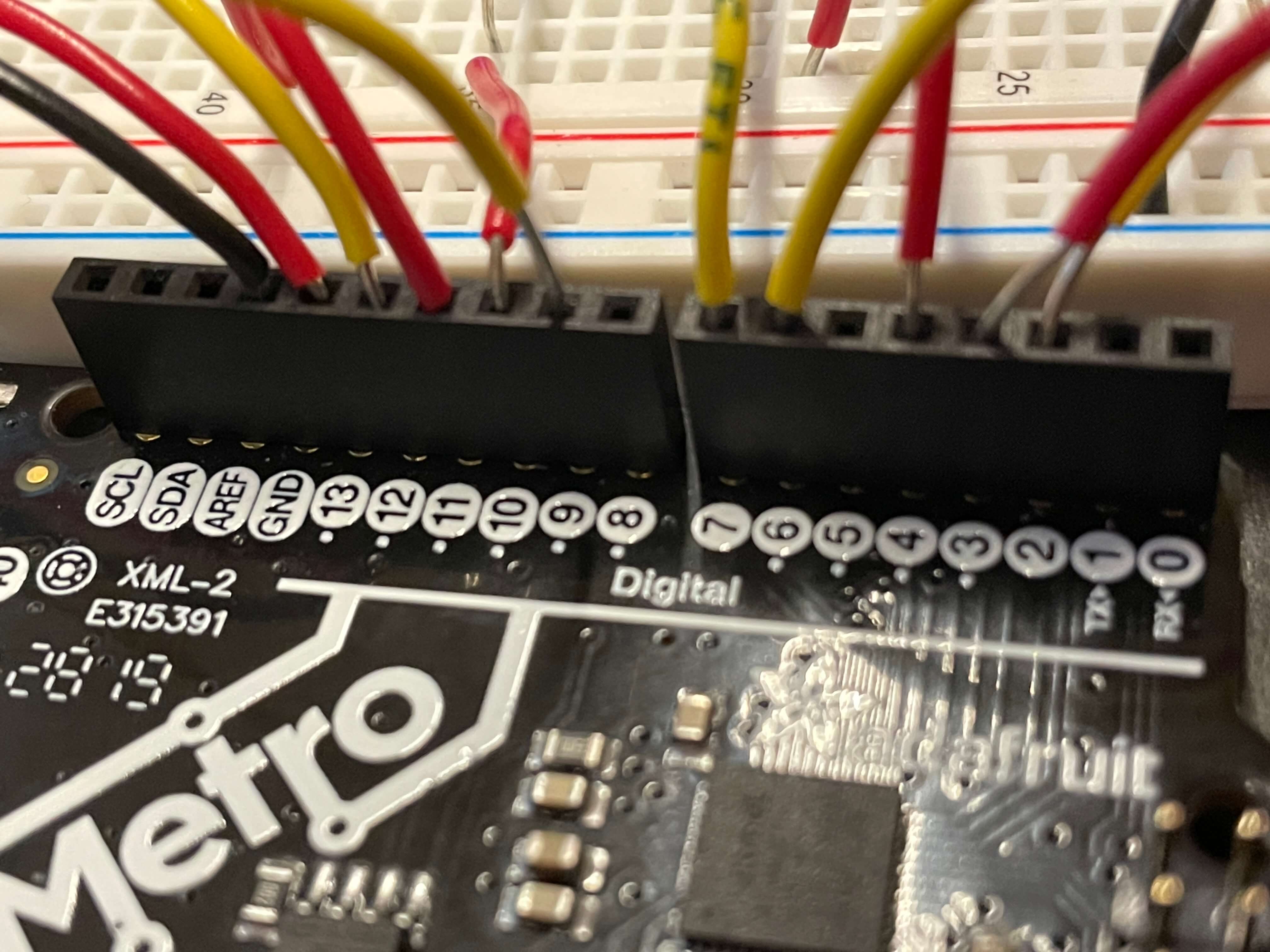
For my circuit, I combined what I learned in all the demos, and added some of my own code. The embeded Arduiono sketch below doesn't include the back two buttons, as that's coming up next after this section. The two images below show the circuit and the pin connections. I color-coded the positive wires: red for LEDs and yellow for buttons. And of course, black for ground. There wasn't any sort of pattern I was following in terms of where I plugged in the wires on the Metro board. For the LEDs, I used 100 Ohm resistors to keep it simple.
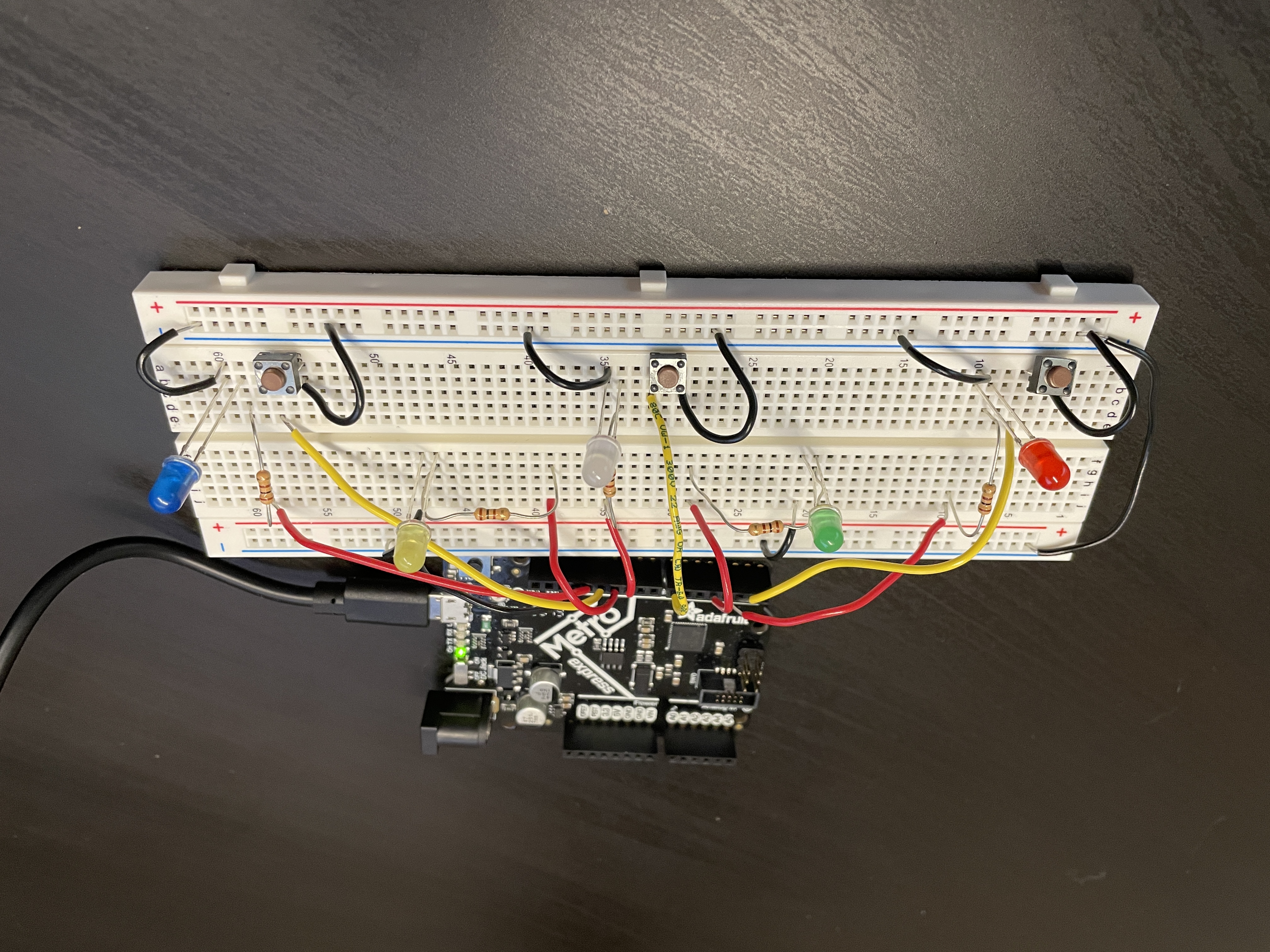
After wiring, the first thing I added to the code was definitons of each button and LED variable pin numbers to their respective names. I also defined the pinMode as either INPUT_PULLUP for the buttons or OUTPUT for the LEDs. After that, I defined three more variables for the button state as either HIGH or LOW.
The gif below shows the three buttons controlling the three front LEDs. This was essentially just taking one of the demo circuit's code we did in class and reformatting it to fit three LEDs.
The next step was to get the back green and yellow LEDs to also work. This was also really simple. I took the demo code we did in class and added it in to mine. But, one thing to note is that I actually double hashed all of the analogWrite(colorLED, 0); and added in else statements after the button press if() statements. I did this because the LEDs would keep flashing on and off when I held the buttons down. I think this happened because the LEDs would be on, but since the loop keeps running, the LEDs flashed off for the analogWrite("color"LED, "pin#"); part.
I also added the final if() statement to make all the LEDs turn on. This was actually the hardest part to figure out, because mine kept not working. The last if() statement says that "if the left and middle buttons are the same state; and the right and middle buttons are the same state; and the middle button state is LOW, then all lights turn on." This can be seen in the gif above.
Lastly, I added code to make sure, for example, when the left and middle buttons are pressed, only the green LED lights up and not also the red and white LEDs. This is shown in the gif above. I made two new if() statement that say "if either the left and middle or right and middle buttons are pressed, then only either of the back two light up by setting the respective front LEDs analongWrite value's to 0, meaning off."
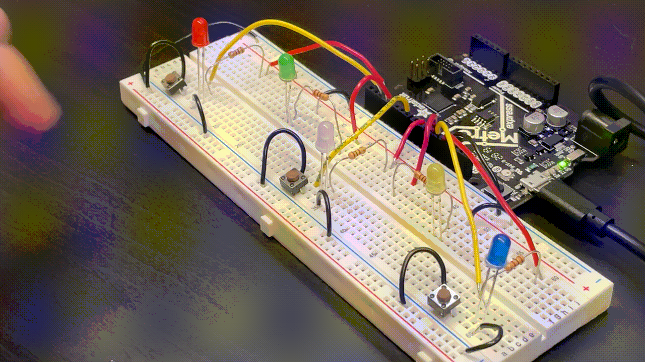
Light Show Circuit V2
Because my V1 code didn't use any for() loops, I added two new buttons which added the actual light show component of my build. For the wiring, I kept the same color code (yellow for buttons and red for LEDs) and used 100 Ohm resistors. All I did on the actual breadboard was just add two new buttons, two yellow wires, and two black ground wires.
The images below show the updated breadboard circuit with the added wires.
In terms of actual coding, I added new variables for the two buttons and added two if() statement to start the LED shows. I did a lot of experimentation with the LED shows by testing out different delays and variable increments. Both LED shows use chains of for() loops to create the brightening and dimming lights in patterns.
The gif above is the show for the back left button. I compiled many of the same for() loops we did in class for each individual LED. This was the first show I made, so I wanted to keep it simple.
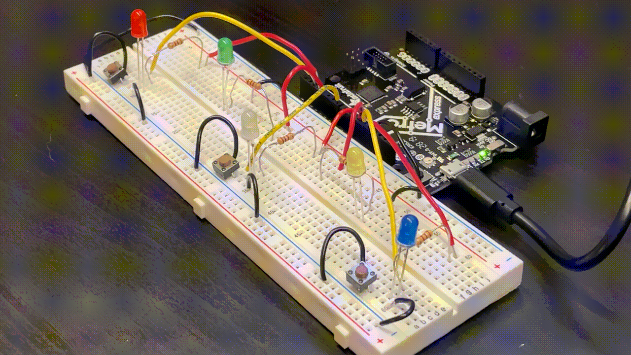
The gif above show the second light show, which is activated by pressing the back right button. This one turned out much better than the first one did because it goes faster than the first one. The inspiration for this show was a firework. The second show starts with two loops (firework launch), then flashes three times (firework pops), and ends with the random turning off (firework fading away).
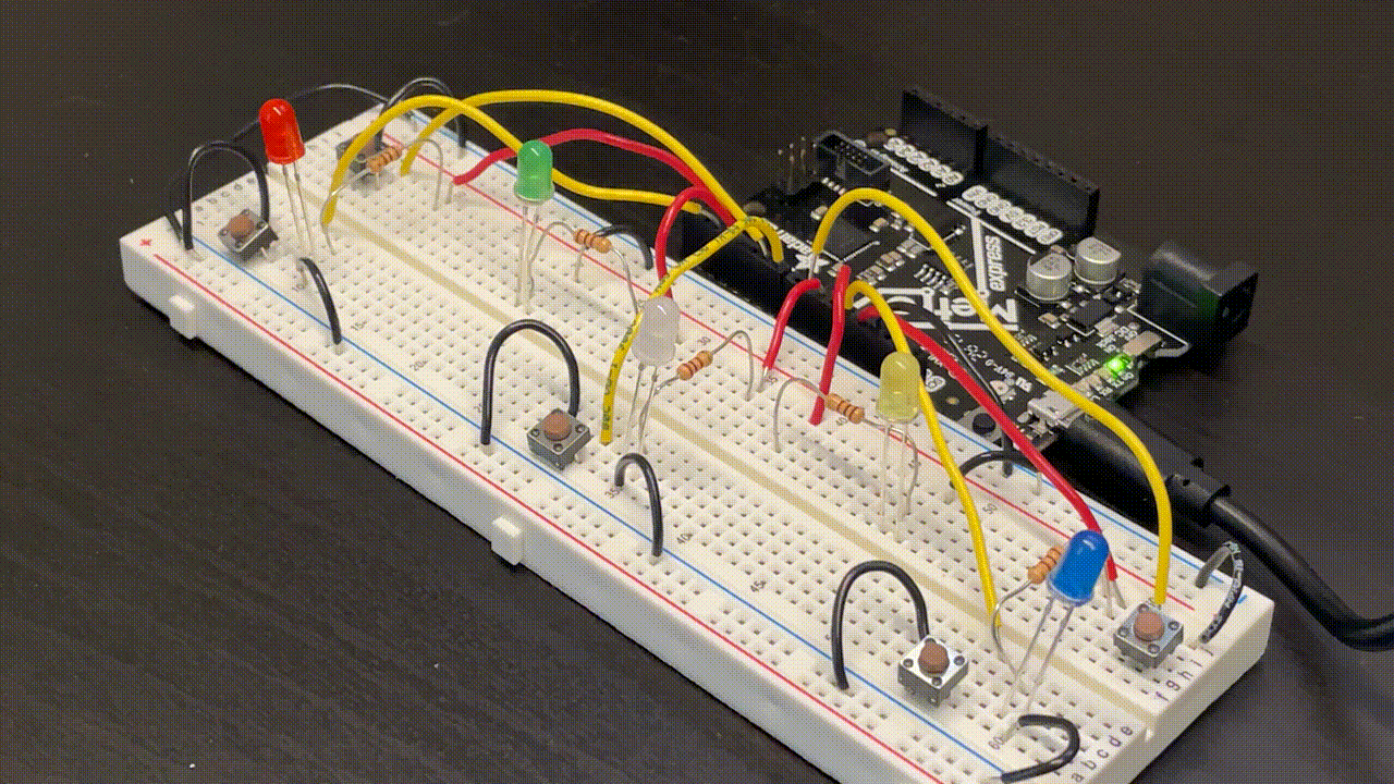
The shows, and the whole circuit in general, look really cool in the dark, so here's the same gif that was at the beginning of the page.
Below are the demo videos of the circuit in the light and dark.
What I Learned
» How to use if() statements
» How to use for() loops
» How to use nested for() loops
» How to use buttons as inputs
» How to set pins as input pullups