What To Do
1a. Make a circuit on a breadboard with components in the kit.
1b. Use a multimeter to measure the voltages in the circuit.
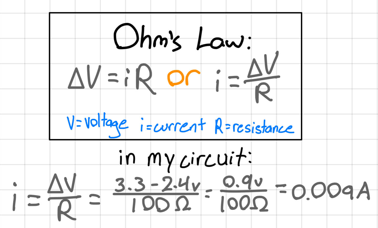
1c. Use Ohm's law to calculate the current through some part of the circuit.
1d. Simulate your circuit on Tinkercad.
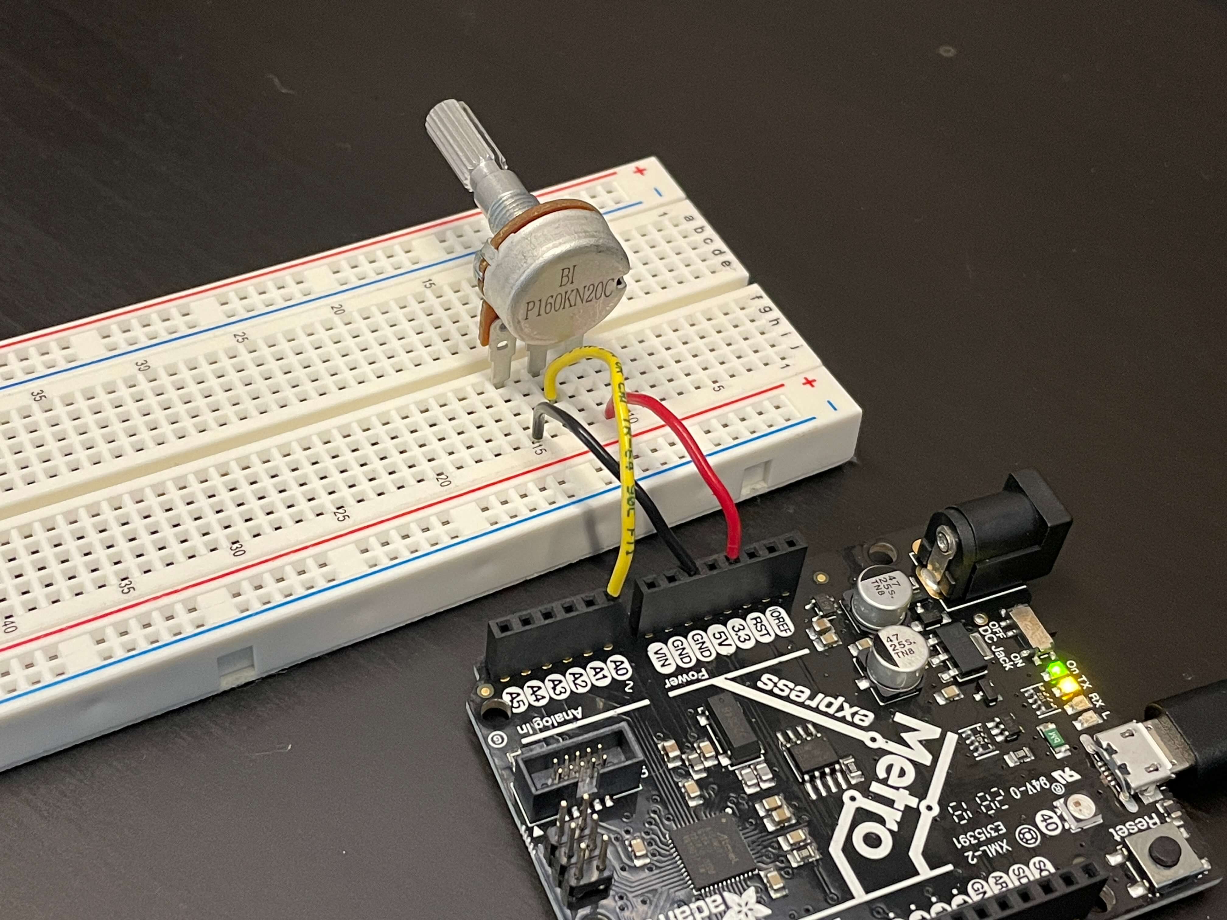
2. Use the Microcontroller Analog in analog-to-digital converter (ADC) to measure the voltage of a potentiometer.
What I Did
In this assignment, I had to learn all of the basics of using breadboards and coding on Arduino, because I had no prior experience with using microcontrollers, breadboards, components of breadboard circuits, or coding using arduino. One valuable resource I used was Tinkercad. I have used Tinkercad in the past to model 3D objects, but I didn't know that it can also be used for creating, coding, and simulating circuits. Using Tinkercad, I made simulations of the circuits I made in real life. I also just experimented on various different circuits using the multimeter to see how changes I made, like swapping resistors, affected the overall circuit.
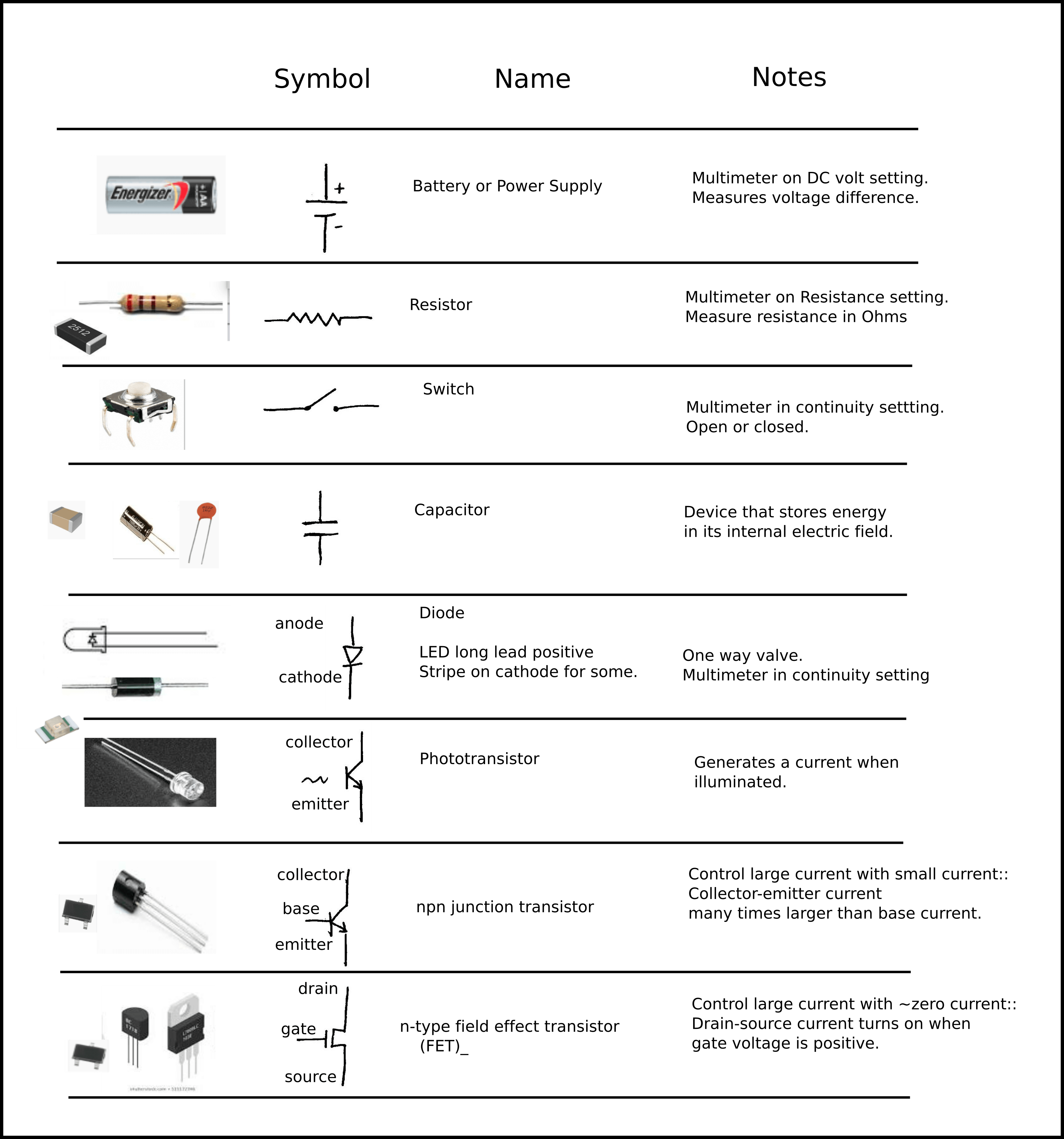
Below is picture of the basic circuit elements that we learned about. This chart came in really handy to learn about each component and what they do. So far, some of the components of circuits that I have used include resistors, LEDs, and a potentiometer. The website that I did a lot of my learning from is linked here.
Basic LED Circuit
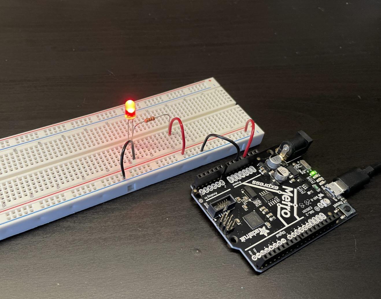
To the right, there is a picture of the circuit demo we made in class. It's a very basic setup and doesn't require any coding. The parts include the Metro board, a 100 Ohm (Ω) resistor, a red LED, and some black and red coated wiring.
On the Metro board, I plugged in the red wire to the 3.3V connector and the black wire to the ground connector. The red wire connects to a 100Ω resistor. The other end of the resistor is connected to the red LED, and then the rest is just connected to ground. One key thing that I learned about the LED is that the anode (the long lead) was connected to positive, while the cathode (the small lead) was connected to ground. For the resistor, polarity doesn't matter. Also, for this particular circuit, it doesn't matter whether I put my positive cable in the 3.3V or 5V. However, if I plug something else into one of the analog connectors, then there is a chance that I fry the board if I plug it into the 5V socket.
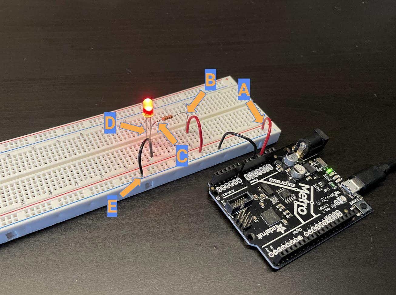
After making my circuit, I measured the voltages at 5 different locations and marked them down. Points A through E are marked on the picture below as well as marked on the schematic drawing of the circuit below. I drew out the circuit schematic for the basic circuit, with the icons representing the Metro board, the 100Ω resistor, and the red LED. I also used Ohm's Law to calculate the current in the system.
Just a quick note, I made the hand-drawn diagrams and did my work on the iPad app GoodNotes 5, and I labeled the breadboard image using Google Slides.
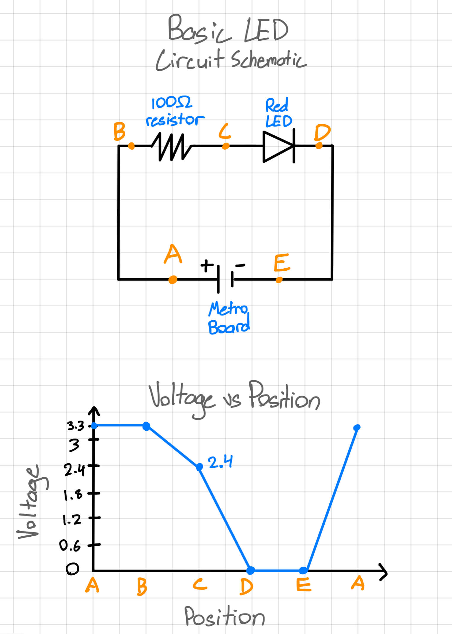
Now, I'll go over and analyze the data I collected. Looking at the first "Basic LED Circuit Schematic" drawing, the circuit modeled directly matches my breadboard circuit. Except, I used the Metro board to power the circuit instead of a battery. Talking a look at the graph, all the numbers I collected make sense when you look at what's exactly happening in the circuit. I used these drawing and pictures to get a better understanding of circuits.
Positions A and B are both before any power-consuming component, like the resistor, so there is no change in voltage. Then, after the resistor at position C, the voltage drops to 2.4 (the actual number was fluctuating between 2.39 and 2.4, so I just rounded up). This means that the 100Ω resistor drops the voltage by about 0.9V. At positions D and E, there is no voltage because the voltage is used by the LED. After position E, the circuit finishes its loop and starts back at 3.3V at position A.
Using Ohm's law, I calculated that the current in my system to be 0.009 amperes (A), or 9 milliamperes (mA). I calculated this by first finding the change in voltage, which was 0.9, and then dividing that by the resistance, which is 100 because of the 100Ω resistor, to get the final asnwer of 0.009 Ampheres.
Blinking LED Circuit
The blinking LED is one of the most common examples of basic Arduino coding. In this circuit, the LED blinks on and off for a set period of time.I didn't have to code anything because the blink code is already an example code that is given by Arduino. Since this was the first time I'd be uploading a code sketch from my computer to the Metro board, I had a few steps on the Arduino software to finish first. To get the code from the editor on my computer to my Metro board, I plugged the board into my PC using a USB to micro USB cable. Then, I fiddled around with the board type and COM settings to make sure it was on the right board. Finally, I clicked "Upload" on the Arduio software.
The way that the light blinking actually works is by the board using a technique for controlling power called Pulse Width Modulation (PWM). The PWM output produces pulses of power of various set time lengths, instead of constant power seen without PWM, which I used to change the status of the LED to either on or off.
The gif above is a vsual of what the blink circuit looks like: the LED on the Metro board flashes on and off. This makes sense because in the code to the left, the pin that is being used as the output is "LED_BUILTIN," which is the Metro board's built-in LED. To get the LED on the breadboard to flash, as seen below, I connected the positive wire to the 13th digital socket instead of the 3.3V socket connector. The reason this works without changing any code is because the 13th digital socket also functions as the "LED_BUILTIN" pin.
Circuit With Potentiometer
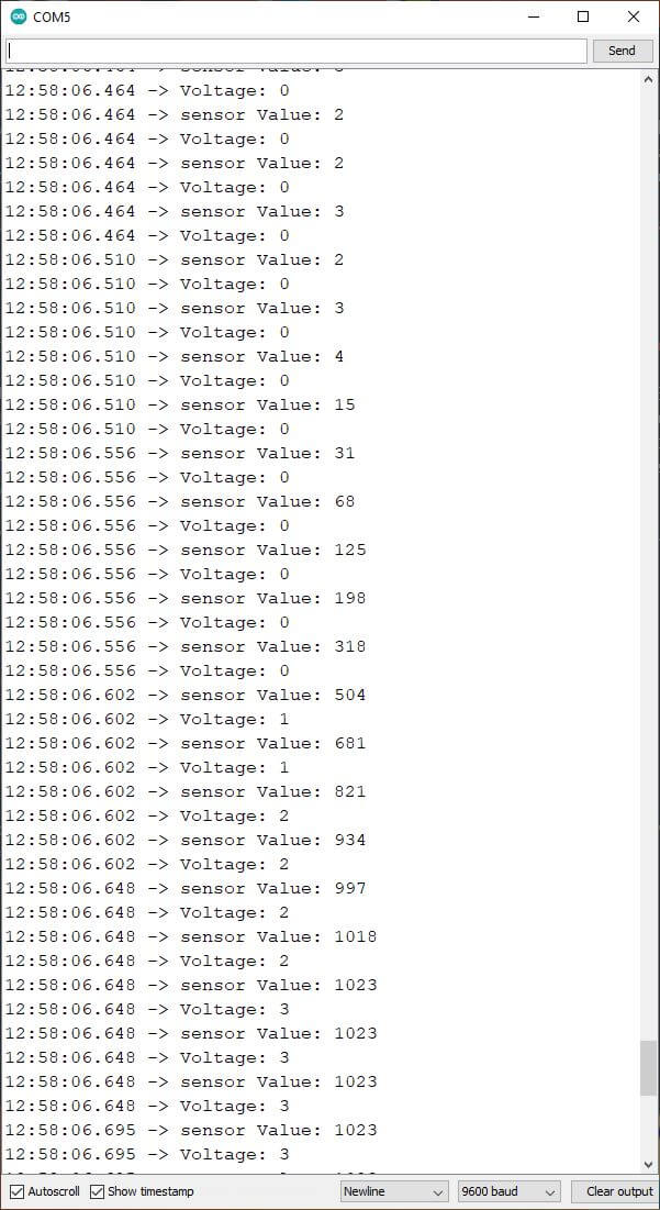
The way that potentiometer works is by a knob controlling how much resistance is in the circuit (the potentiometer is a variable resistor). So, if the knob is turned all the way to the left, depending on the polarity of the poterntiometer, the output would be close to 0. And if the knob is turned all the way to the other side, the output will be 1023. Likewise, if the knob is turned to somewhere in the middle, the output would directly reflect the knob's position in relation to the 0-1023 scale. In the Arduino embed below, there are two different analog read serial codes. We edited the example code, so when we looked at the serial monitor (what was being outputted from the analog 0 socket), it would show a normal voltage number instead of a unitless value from 0-1023. I talk more on this below.
Looking at the code above, the edits we made to the example code are to make the serial monitor output also produce a numerical voltage amount, instead of just numbers from 0 to 1023. For example, the way we converted the 1-1024 scale to a 0-3.3V scale is by adding in this line: Serial.println(map(sensorValue, 0, 1023, 0, 3.3));. The map function is used as the converter, so the 1024 scale is just scaled down to a 3.3V scale.
The reason the voltages appearing on the right are integers is because I have it set in the code to produce integers. I tried making it produce fractional values so it would produce an exact decimal range from 0 to 3.3, but when I tried, it didn't work.
Also, the reason the "sensor Values" range from 0 to 1023 is because the Metro board we are using uses 10-bit Analog to Digital Conversion (ADC). This means that the values produced are a 10-bit range of 1024 quantifiable numbers that we can convert to other scales to measure other values, like voltage. Also, the reason the range I used is from 0 to 1023 is because including 0, the range from 0 to 1023 is 1024 numbers.
Circuit With Voltage Divider
Voltage dividers were also something we learned about during the lab session. I learned that they form the basis for different types of sensors. The circuit I made is a very basic model of how a voltage divider works. Understanding how this basic voltage divider works was really helpful when comparing my circuit data to other circuit's data to see how different components affect the voltage at different points of a circuit.
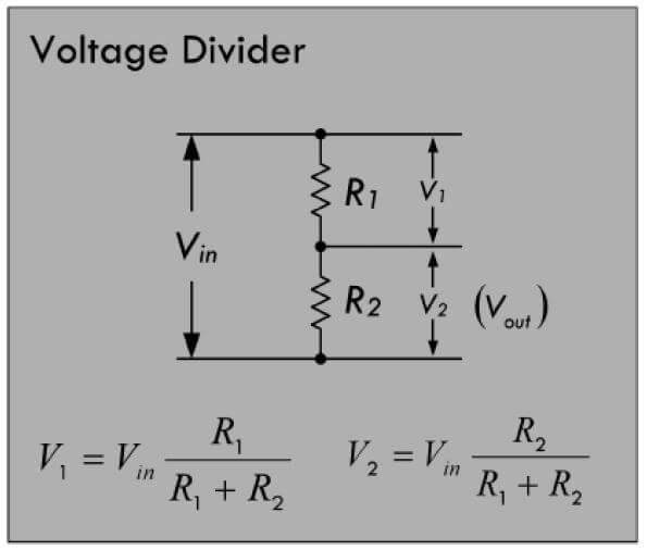
The Voltage Divider diagram on the right is what I folowed to make my circuit. The equations below the diagram work interchangably, meaning you get the same answer by using either equation with either resistor being R1 and R2. The circuit is shown in the first image below.
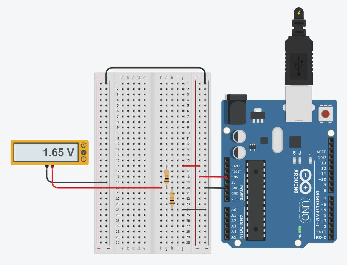
I learned that if the resistors have the same resistance, for example, if both are 10kΩ resistors, then the voltage between the resistors will be exactly half of the system input. In my circuit, I made the system input 3.3V, so the divided voltage is 1.65V. The math also checks out. If we take a look at the V1 equation (to find the voltage between the two resistors), R1 and R2 in my circuit are both 10kΩ, so R1+R2 is 20kΩ. This simplifies to 1/2. One half of 3.3V is 1.65V, which is what the multimeter shows. Likewise, that also means that the V2 equals 1.65V, because it has the same variables as V1, like voltage and resistance. This means that after the second resistor, there are 0 volts left.
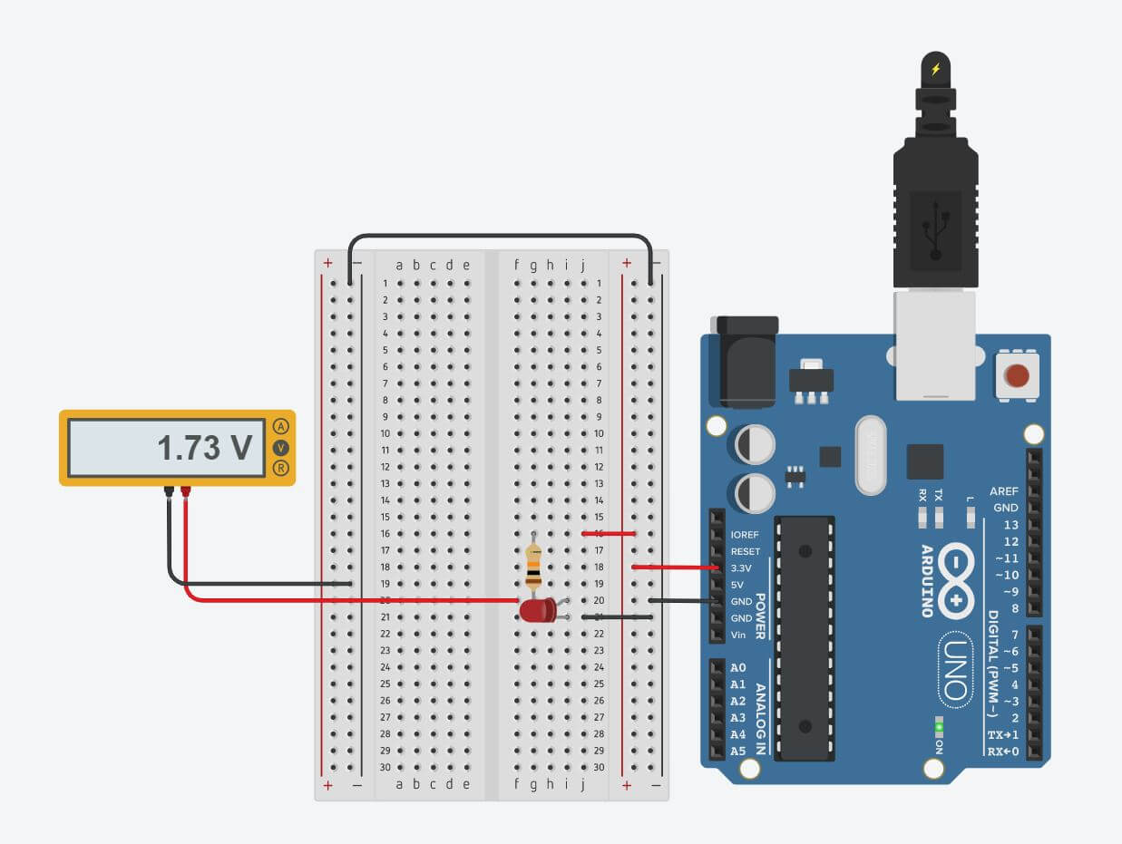
Like I said before, the voltage is only split exactly in half between two resistors when the resistance of the two resistors is the same. This is proven in the second image above with the red LED replacing the second resistor. The voltage after the first resistor is 1.73V, which is not half of 3.3V. The LED is using more volts than the second resistor is in the first image, which is why the voltage just before the red LED in the second circuit is higher than the voltage before the second resistor in the first image.
What I Learned
» What volts, current, and amperes are
» How to circuits on a breadbaord
» How to circuits on Tinkercad
» Components of circuits
» Why potentiometers can be used as variable resistors
» How to measure voltages using a multimeter
» How to calculate current using Ohm's Law
» Very basic Arduino language coding
» How to use serial monitor to recieve active feedback from analog connections