What To Do
1a. Make and document a kinetic sculpture.
1b. Control the sculpture with a circuit on a breadboard that uses components in the kit.
2a. Use a multimeter to measure the voltages in the circuit.
2b. Use Ohm's law to calculate current through the circuit.
3. Use the Microcontroller Analog in (ADC) to measure the voltage of a potentiometer.
4. (Optional) Use tools like Tinkercad to simulate the circuit.
What I Did
For this assignment, my kinetic sculpture was a foamboard plane with lights that has some degree of roll using cams. I learned a lot of different things when it comes to using the Metro board, coding on Arduino, troubleshooting Arduino code, etc. This was probably my favorite project out of the three we have done so far, as it incorporated many different facets of digital fabrication, like making a physical model, writing up your own code, troubleshooting your model, and much more.
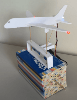
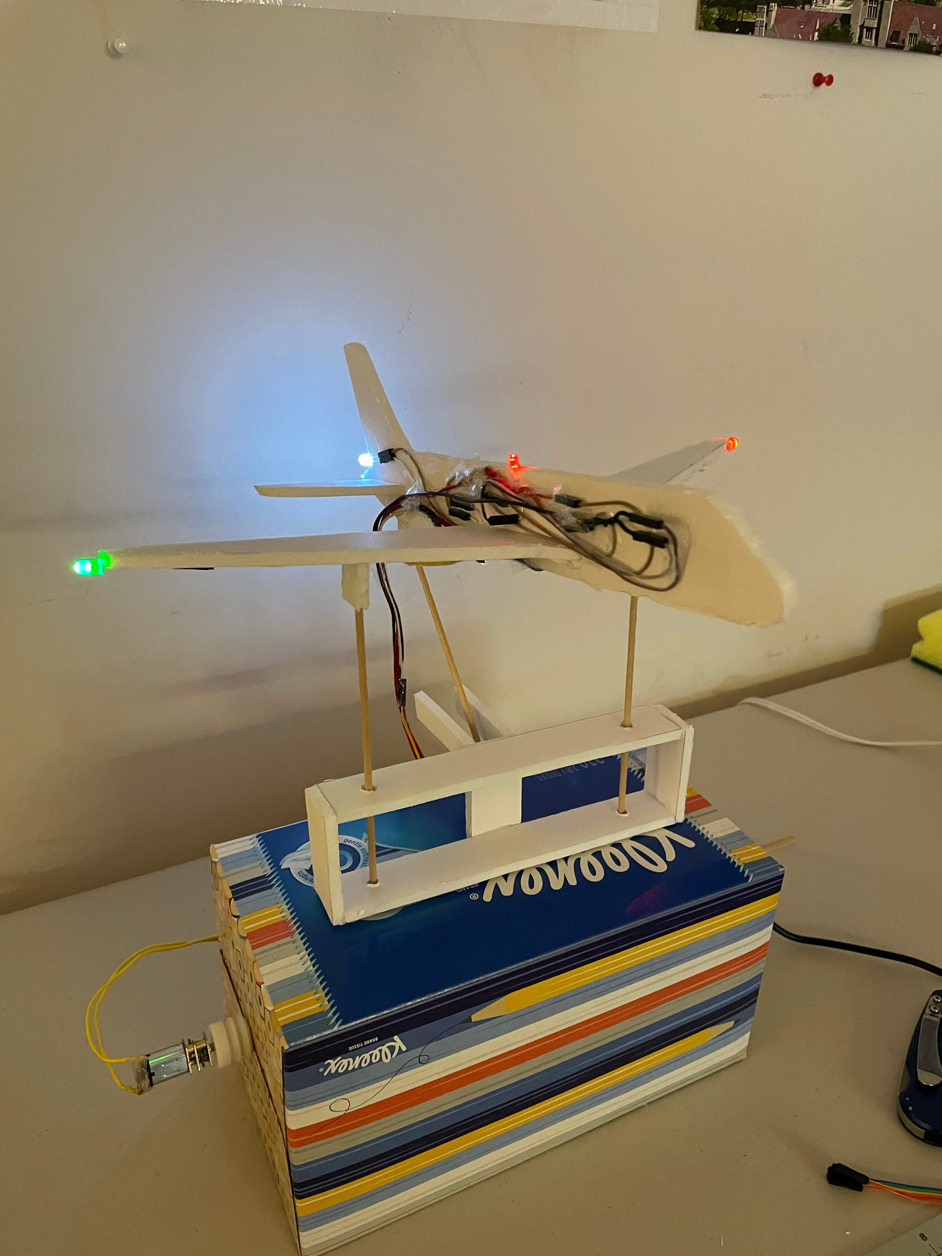
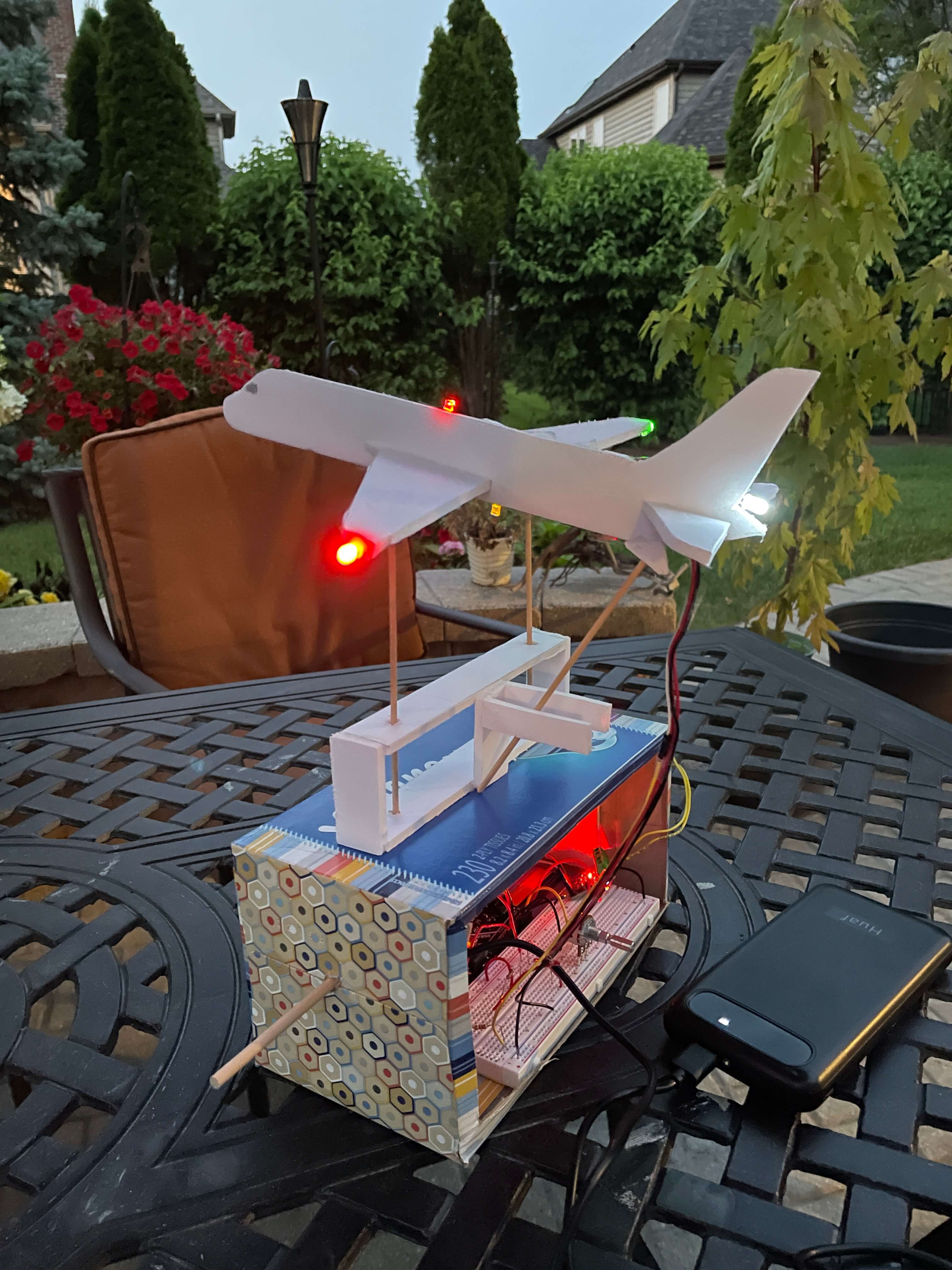
On the right is a gif of my kinetic sculpture in action. My sculpture is a model of a plane "flying" with use of a rotating cam system and some LEDs. The whole thing took about a day to make, including the wiring and coding. There are three main parts to the whole build: the plane, the box, and the electronics.
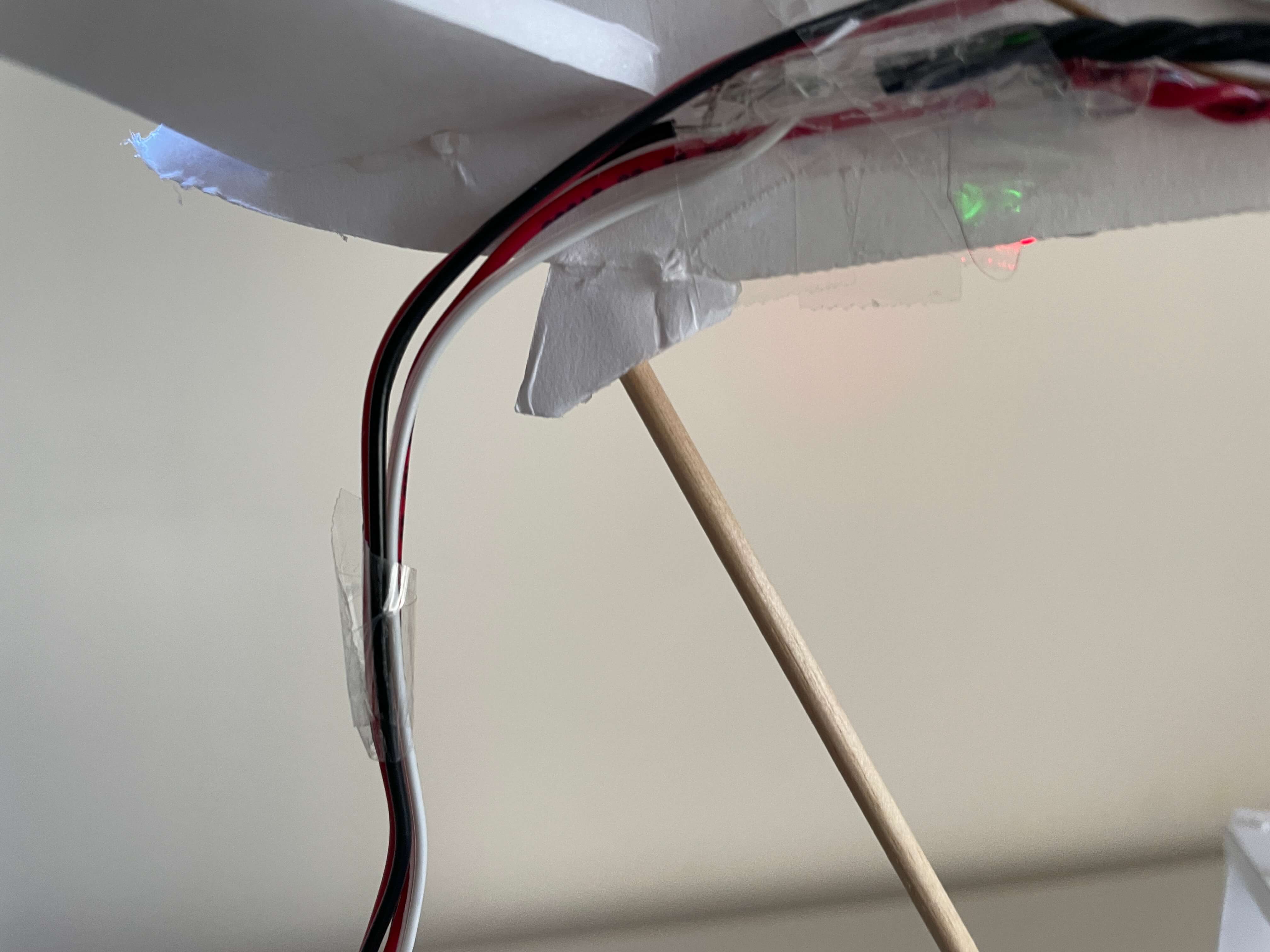
This gif is taken in what I call the "main view" perspective. In this main view, the viewer sees the front part of the plane and box. There are minimal wires in the view, although in this gif, you can see a few wires just on the underside of the plane, and of course, the group of wires that hangs off of the back. For that back group of wires, I wanted to hide them as much as possible, but because I liked the openness of the whole sculpture, I didn't make a background to cover up the wires.
Because I wanted to keep the design simple, I didn't add any pictures or a cover to the Kleenex box. I think the final product turned out really well, especially because of how plain it is. There isn't any fluff in the design either, all of the pieces I incorporated into the sculture is there for a reason. For example, just above the Kleenex box, there is the cam follower guide made out of foamboard. Although I made the component look nice with neat cuts and adhesion, the functionality of the piece is what matters, and it works just as it should.
First Sculpture Idea
My plane kinetic sculpture idea is actually the second idea for what I wanted to make for this assignment. My first idea was a drawing robot. I really wanted it to work, but it kind of did and didn't. I talk about what happened and its shortcomings below.
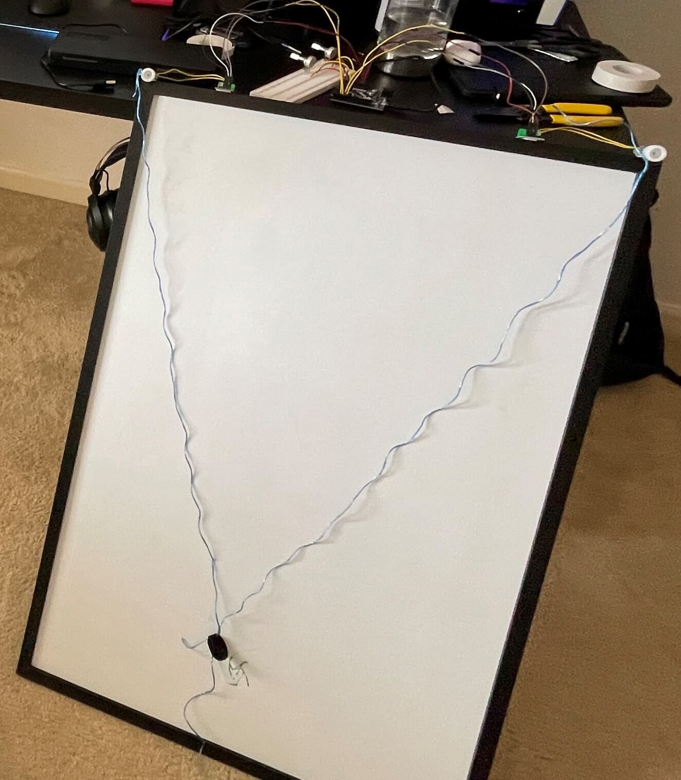
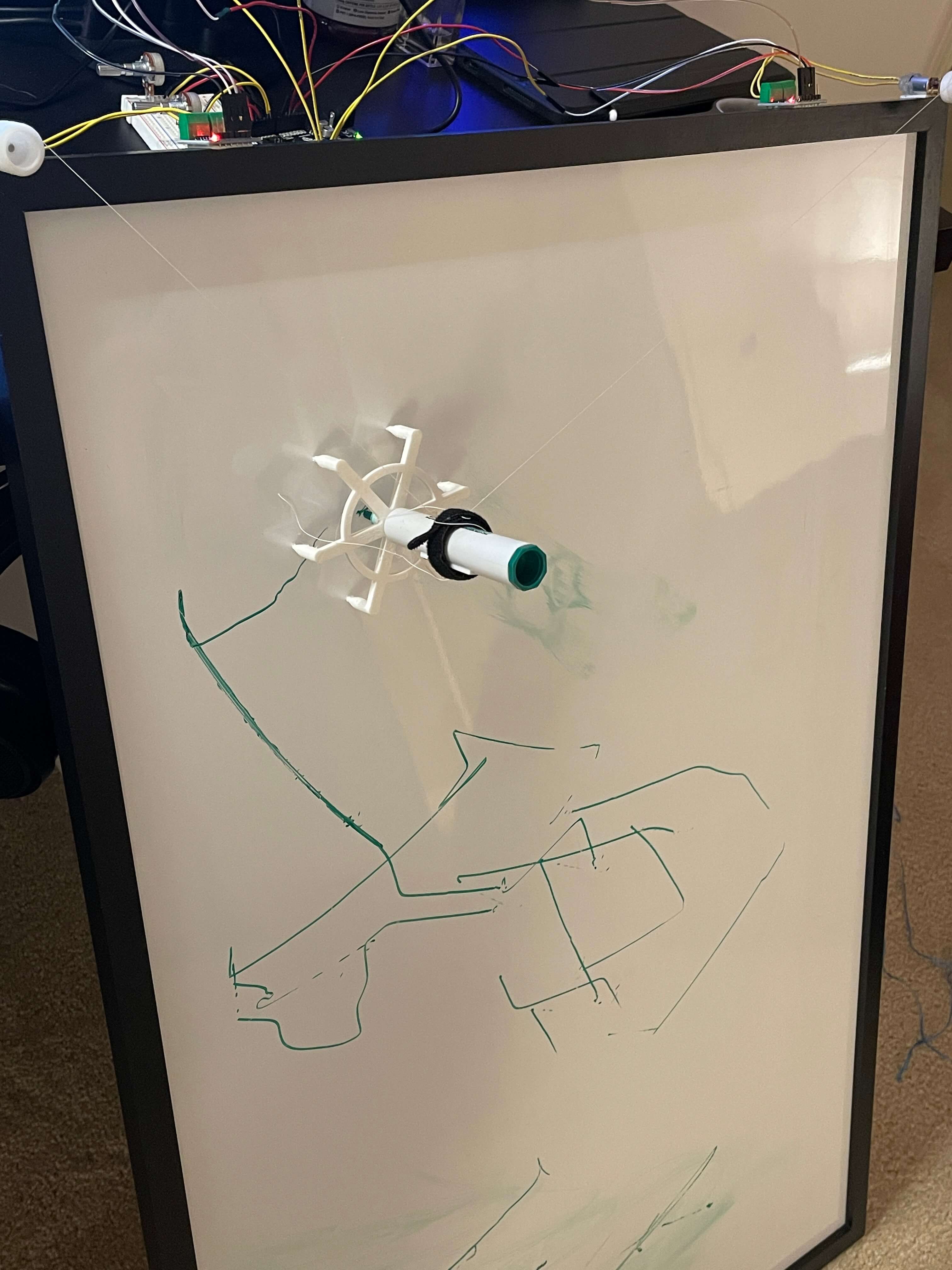
This is my first drawing robot prototype. I say "robot," but it actually requires human control to work. It used two DC motors and two potentiometers to control them. Overall, the code ran fine. I just duplicated and mirrored the code for using the potentiometer to control a motor that we created last week so that it would work with two potentiometers instead of only one.
In the image to the right, I used thread instead of blue twine and I designed and 3D printed a hexagonal marker holder. Both improved the drawing performance a little, but the accuracy of the robot was still too poor to create drawings.
I think the biggest reason it didn't work out was because it was just a bit too ambitious for my skill level of using new software and hardware that I've never used before. Not to mention, I just jumped right into it without really making a small-scale prototype. The dimensions of the whiteboard are about 2 feet by 3 feet. The size only added to my struggles of getting the drawing mechanism to work... properly. Like I said, I got the potentiometers to control both motors, but it was still very hard to control simultaneously because of the lack of any axes. Because there were no X and Y axis that the marker would ride on, the marker would move in curves. The motors would turn and roll up the string, so whatever the length of either string is at a certain point is the radius of the curve that the marker would move in.
Second Sculpture Idea
My second idea was to do something with eccentric cams. I have had prior experience in making a sculpture using cams in school, but all the parts were given to me and cut perfectly from laser-cutting machines. I wanted to create my own cam sculpture and add my own twist to it, which I did by adding in the LEDs.
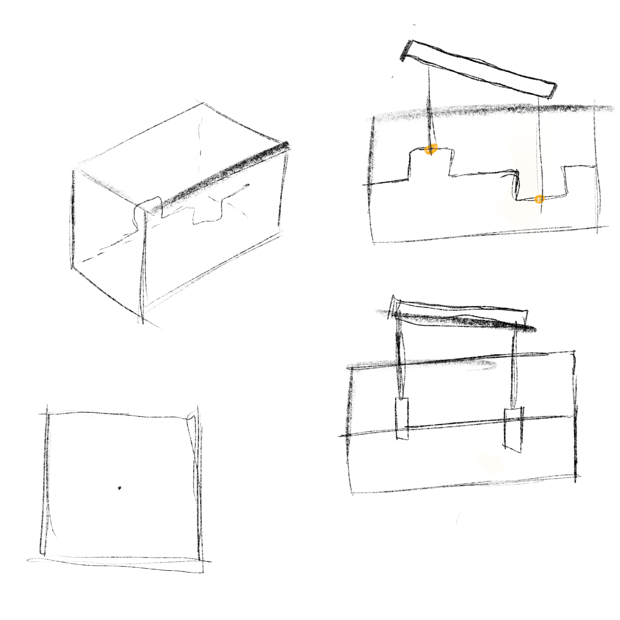
To the right are my brainstorm sketches. At first, I wanted to bend a coat hanger in a way where the whole axle of the cam mechanism was also bent into the cams themselves, as seen in the top-right sketch. But, I figured that connecting an end of a coat hanger to the DC motor would pose to be a challenge, so I decided to go with the normal cams on an axle, as seen in the bottom right sketch.
By this point, I still hadn't decided what to put on the top of the mechanism (what actually moves). I am really interested in model planes- as I have many model planes and LEGO planes as well- so I wanted to somehow get a plane to move on the mechanism. At first, I wanted to make the plane bob up and down, like a rollercoaster. However, I thought that making the plane roll side-to-side would look a lot cooler, so I went with the second idea.
The Structural Build Process

I used this Airbus A380 schematic to draw out the pieces of my plane. To download the schematic, you can just save the image to your drive by right-clicking it. I didn't directly copy the schematic, though. I freehanded the whole thing, so I'm sure none of the parts are proportionally accurate to the real plane at all. But, my pieces still turned out really well. I used a folding utility knife to cut out all the foamboard pieces on a Fiskars cutting mat.
Because I wanted to keep the plane model simple, I just went with creating a "cut-out" plane using the top and side views. This way, the plane had the least amount of pieces possible, but all together, the pieces still resembled a plane.
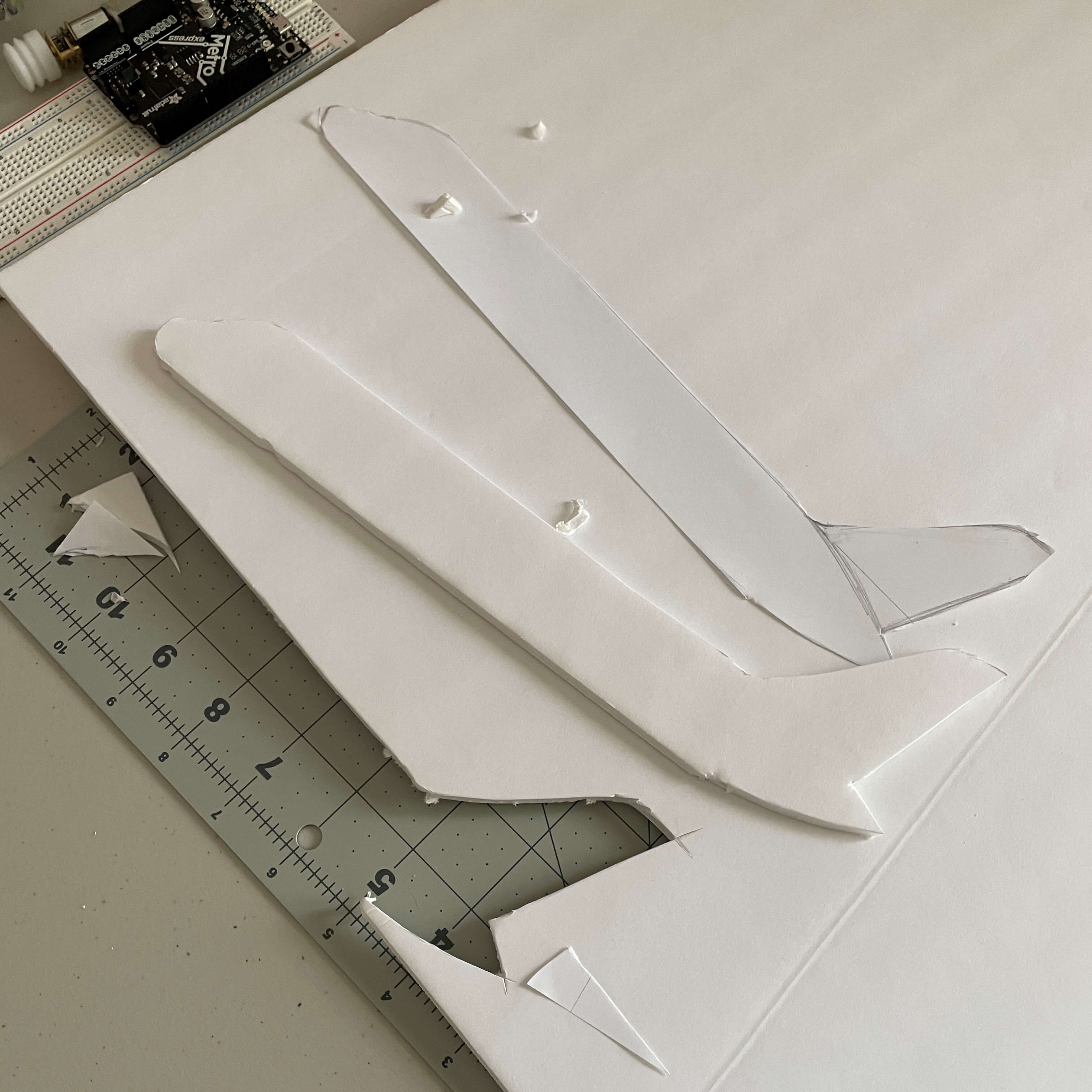
On the left is an image showing how I did the piece cutting. I first drew out the plane parts on a sheet of printer paper. Then, I placed the paper on the foamboard and cut out the plane part. I did this for all plane parts.
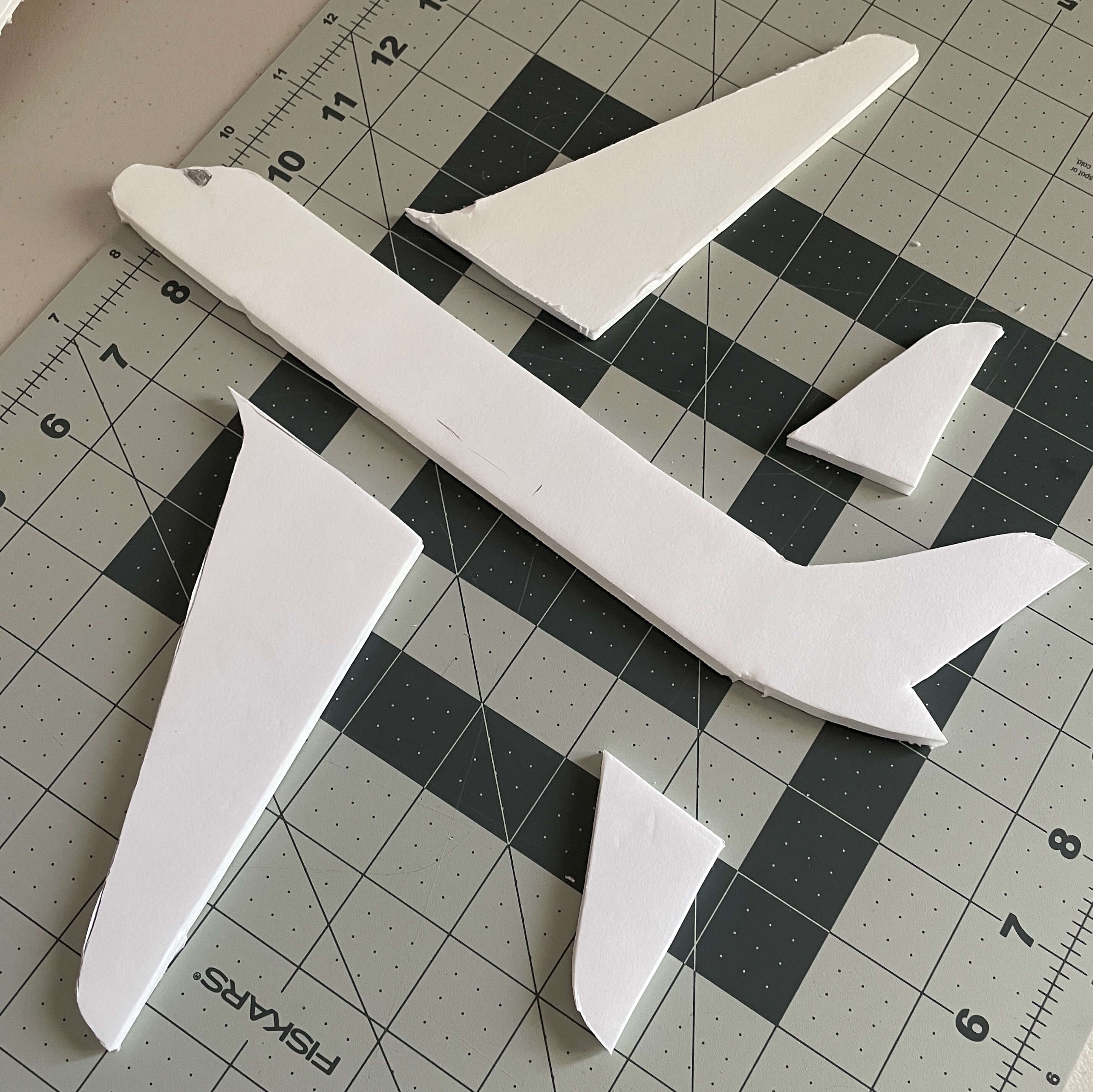
On the right is a picture of all the plane parts laid out. Like I said, because I free-handed the plane part drawings, I'm not sure how accurate the pieces actually are. But, as a whole, it looks fine. To attach the pieces to eachother, I used hot glue.
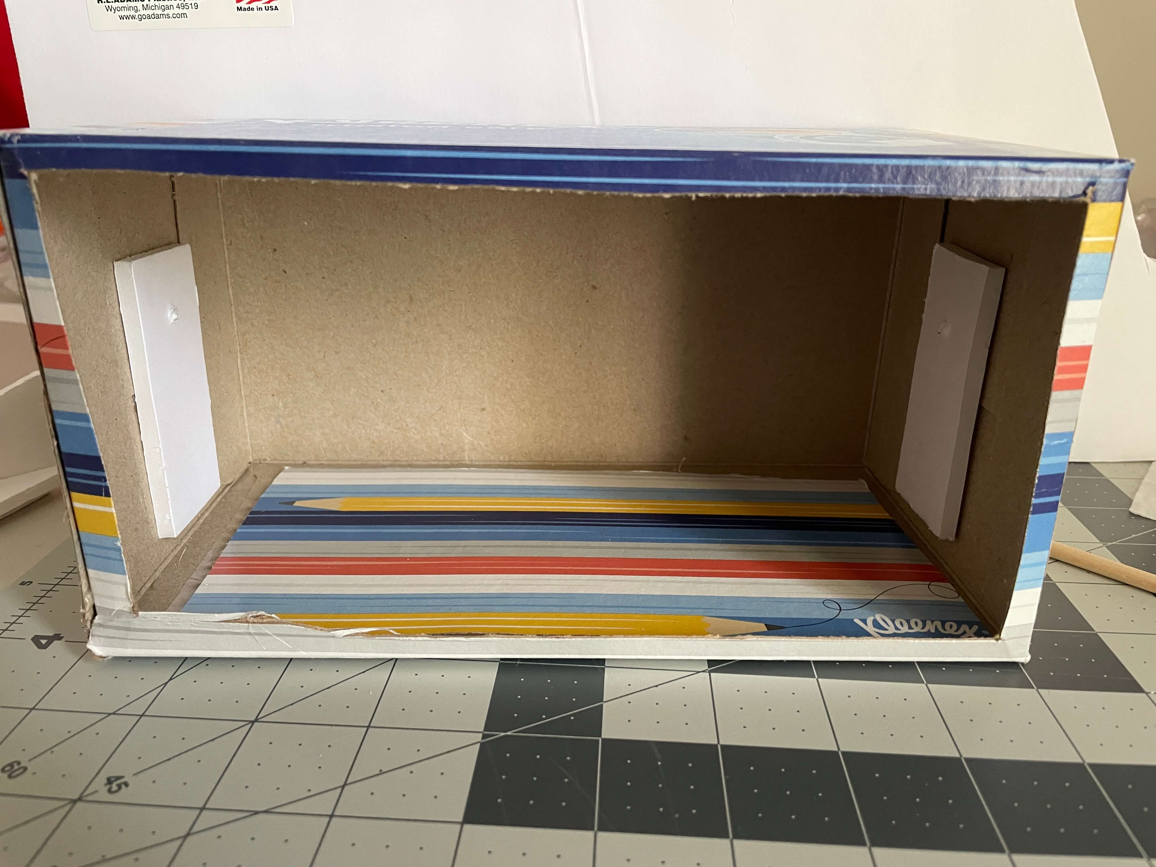
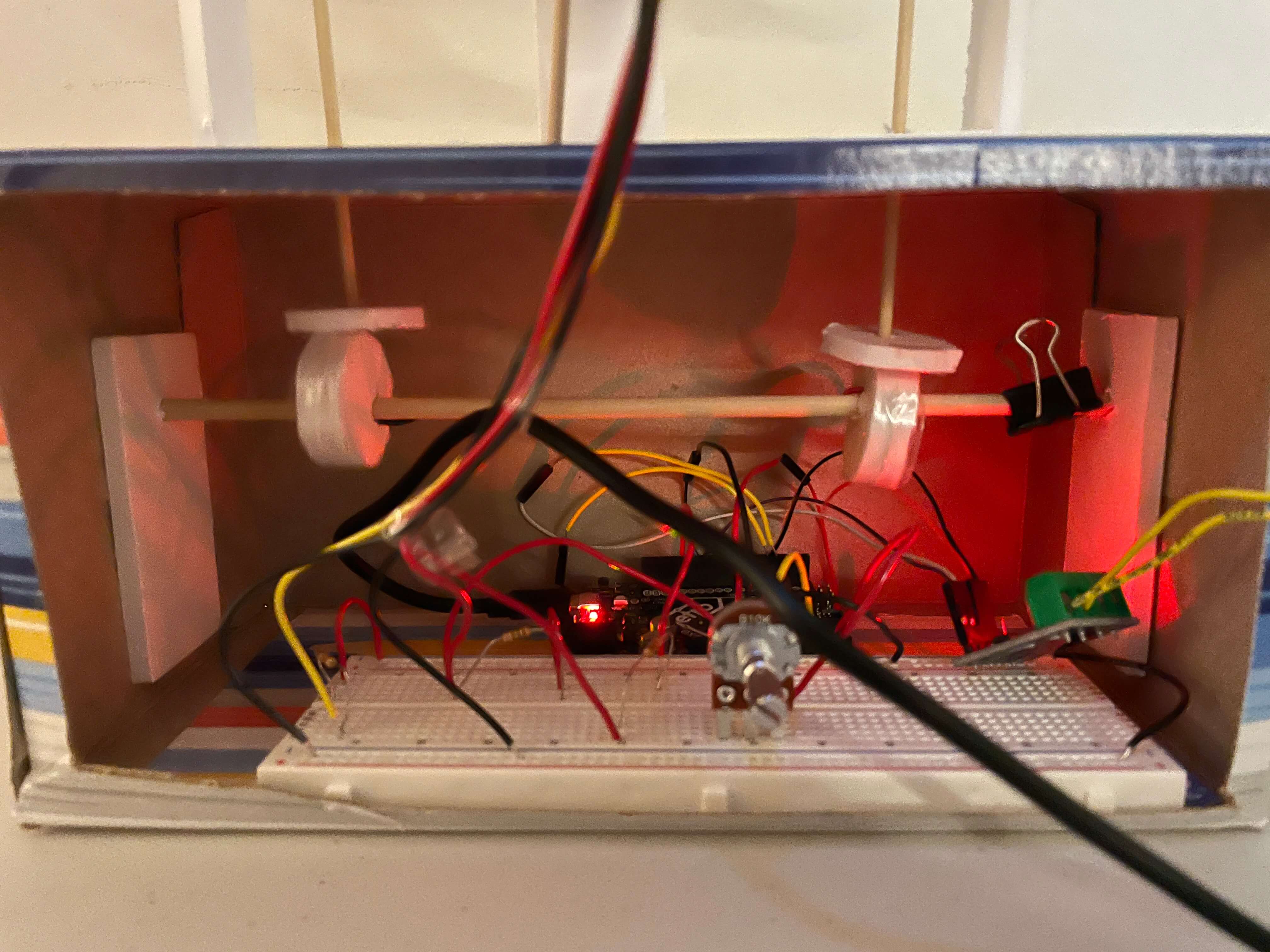
After finishing the plane, I moved on to the base. I used an empty Kleenex box and reinforced the sides with some foamboard scraps. I turned it upside down, cut out one side, and glued that side to the bottom, which was the old top. This way, if I needed to hot glue something to the bottom of the box, I could.
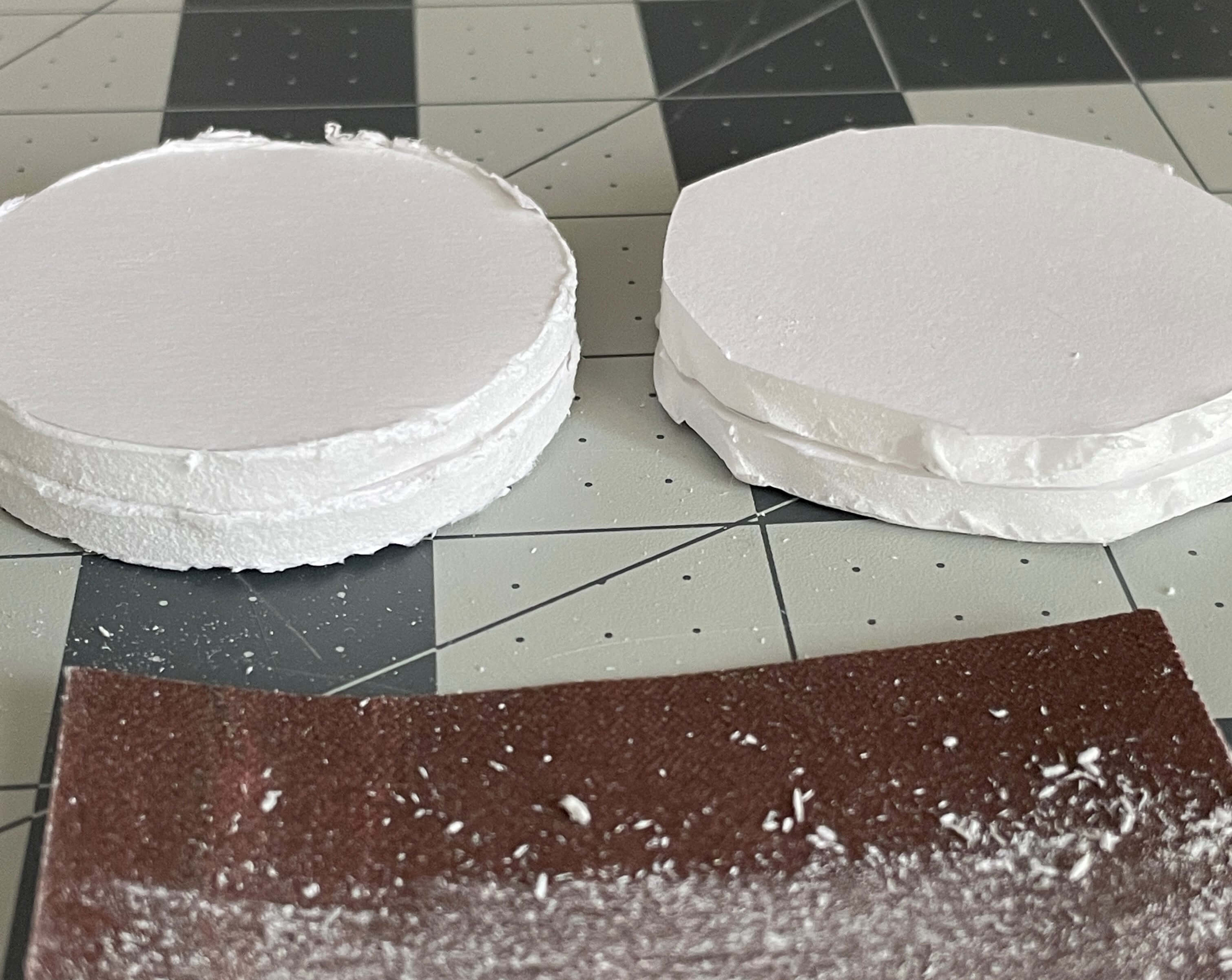
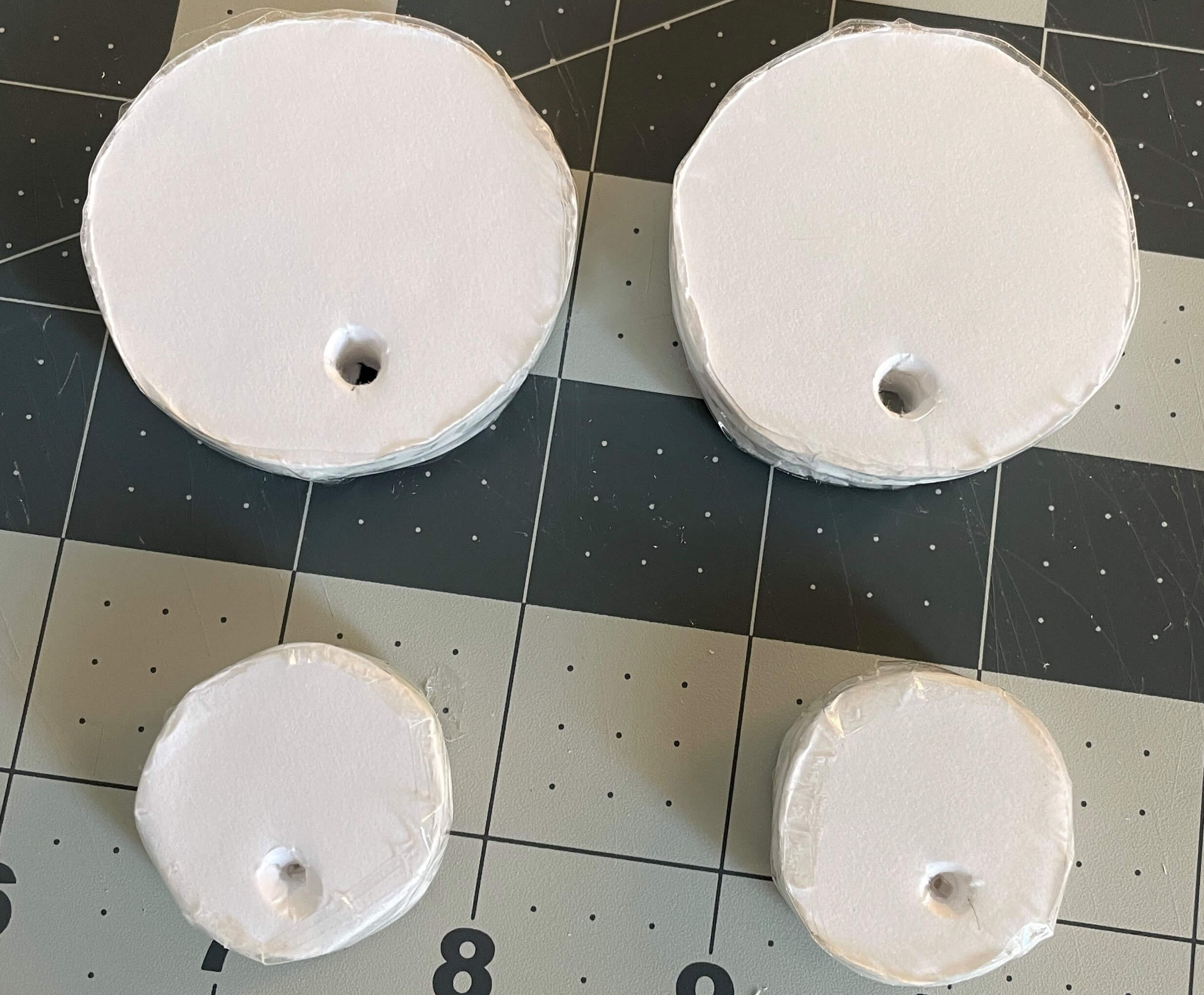
I then made the cams and started doing test runs with and without the plane. I made the cams by cutting out circles from the foamboard; sanding the sides so they would be smooth; gluing two circles together to create a larger surface area for the cam follower to slide on; and finally taped the sides so that the surface would be extra smooth.
Originally, the cams I made were about 2 inches in diameter. This proved to be way too big when the plane started looking like it was in extreme turbulence every time the axle spinned. The cams sometimes didn't even spin because the following dowel just wouldn't go up. So, I downsized so that the diameter of each cam was 1 inch. It's only a 1 inch difference, but that small difference is huge in terms of how smooth the whole cam mechanism runs.
To connect the cams to the wings of the plane, I used thin wooden dowels called followers. I made a small foamboard squares on the plane to stick the dowels into. The two square pieces can be considered the engines of the plane. I connected the follower dowels to the cams by sticking the other end of the follower dowel through small, circular foamboard pieces that are perpendicular to the follower. I didn't use any adhesive here so that I can later easily remove the plane from the box.
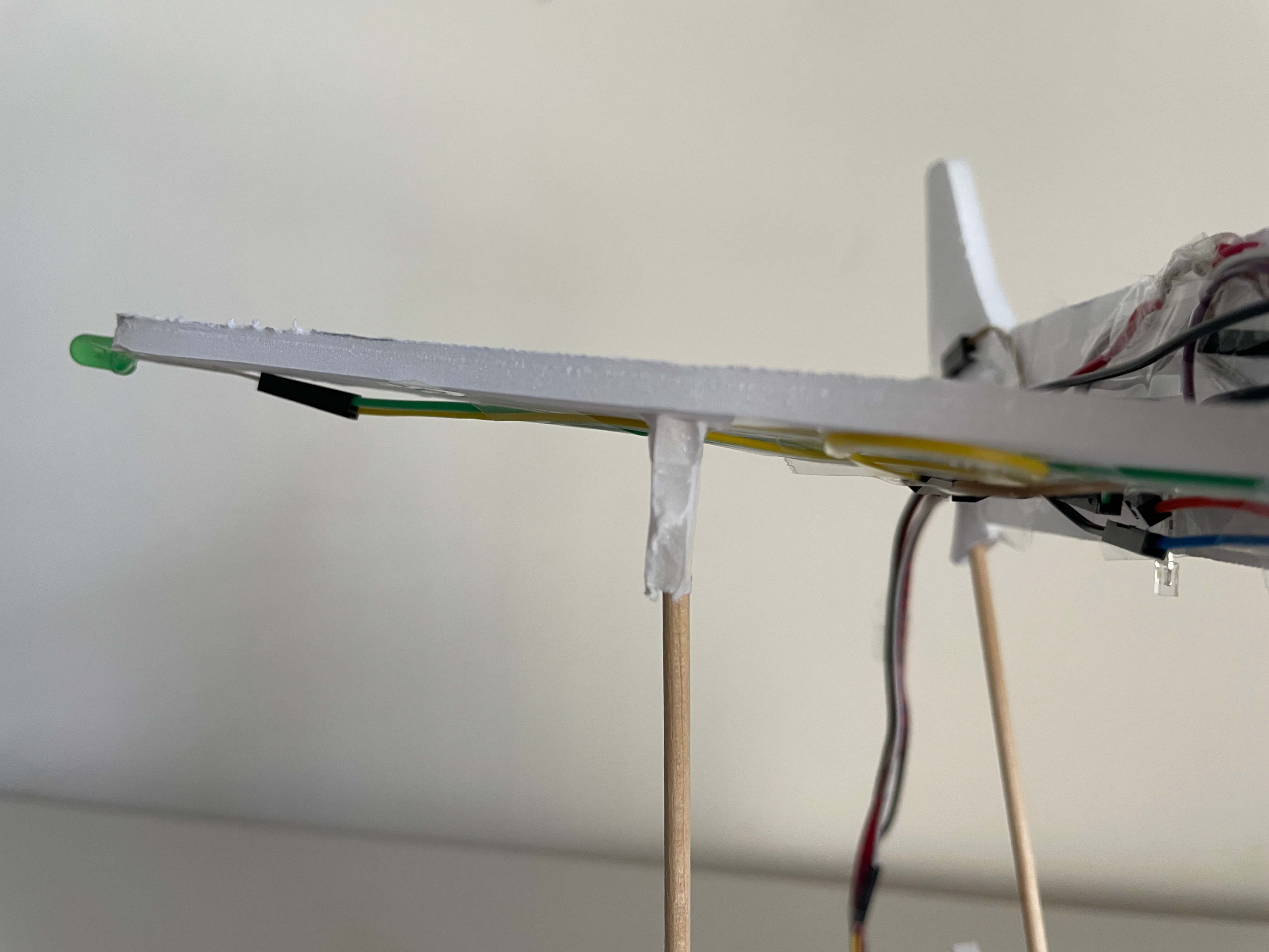
I added a guiding part made out of foamboard to the top of the box. This helps ensure that the followers are sliding vertically, with little-to-no wiggle. I also added a third dowel to the back of the plane, which angles downwards towards the box. The third dowel isn't a follower, as it isn't moving with the cams, but it is there to help keep the plane stable. It isn't attached to anything besides the plane itself, so it just slides up and down the foamboard piece.
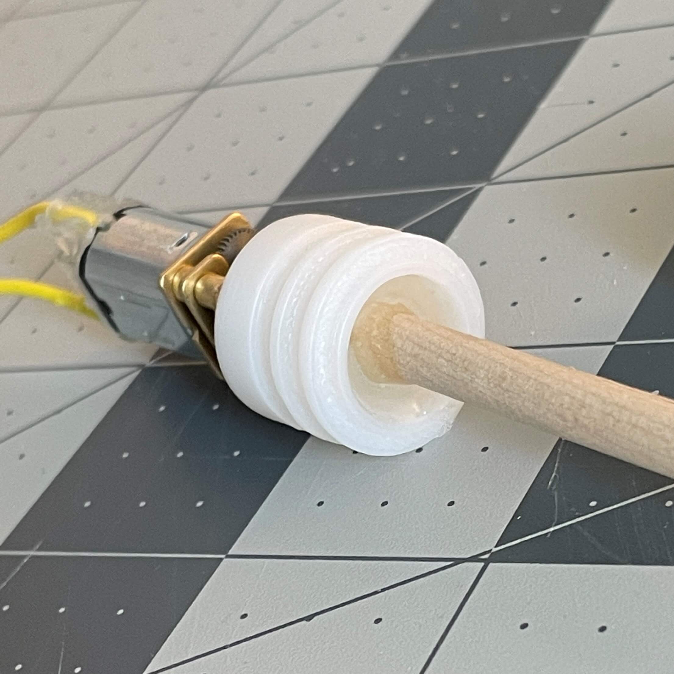
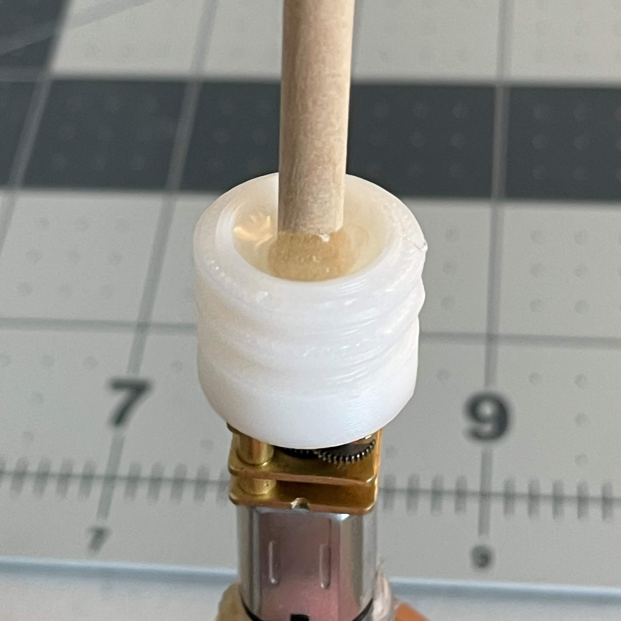
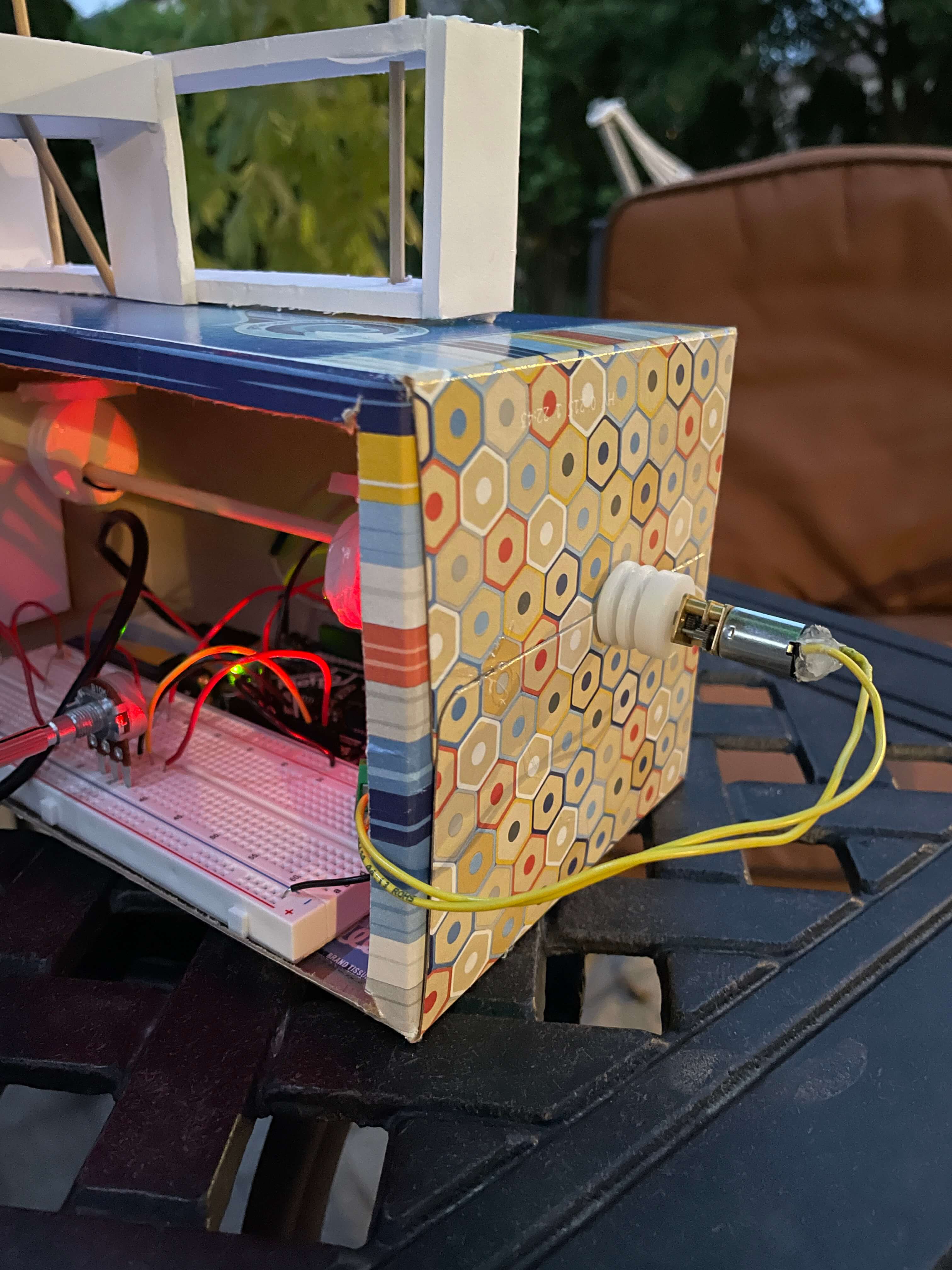
I used a DC motor to spin the main axle. I attached the motor the the axle by first inserting the 3D printed inner LEGO wheel piece included in the kit onto the motor shaft. Then, I used hot glue to attach the dowel to the center of the wheel piece.
Also, nothing holds the motor on the outside of the Kleenex box. The wires are stiff enough for the motor not to spin itself. To make sure the wires don't rip off of the motor, I used hot glue to cover the wire connections on the motor.
The Electrical Build Process
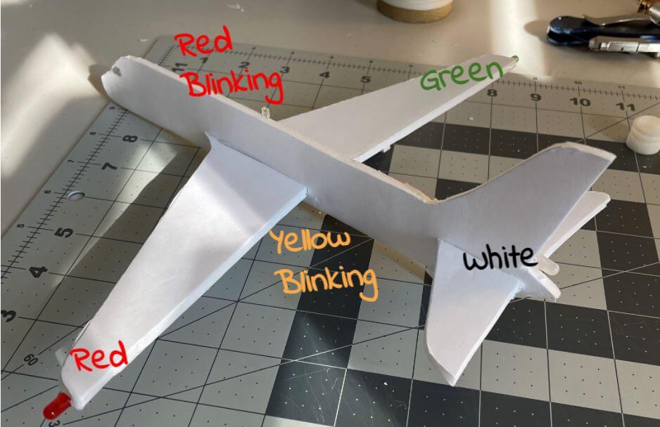
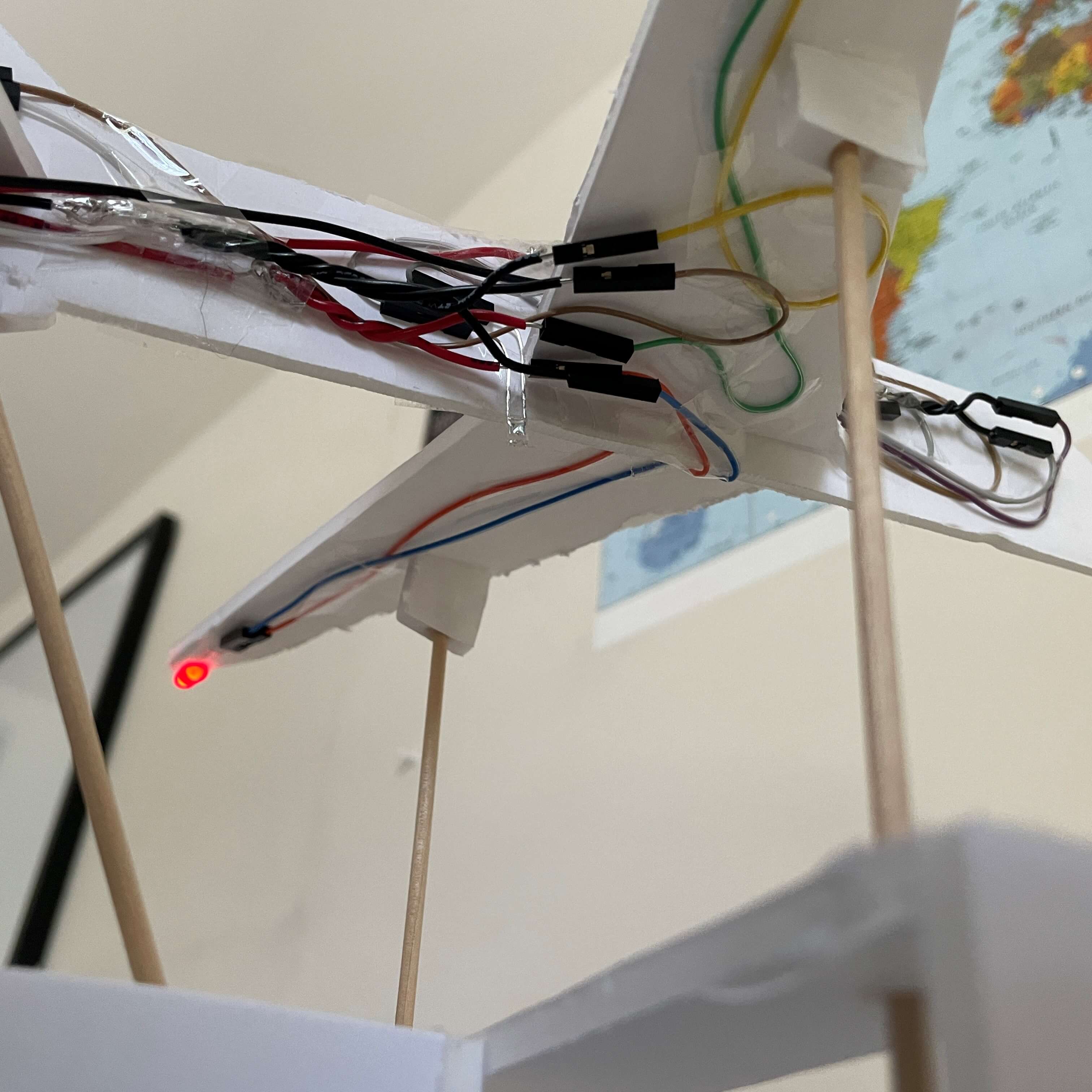
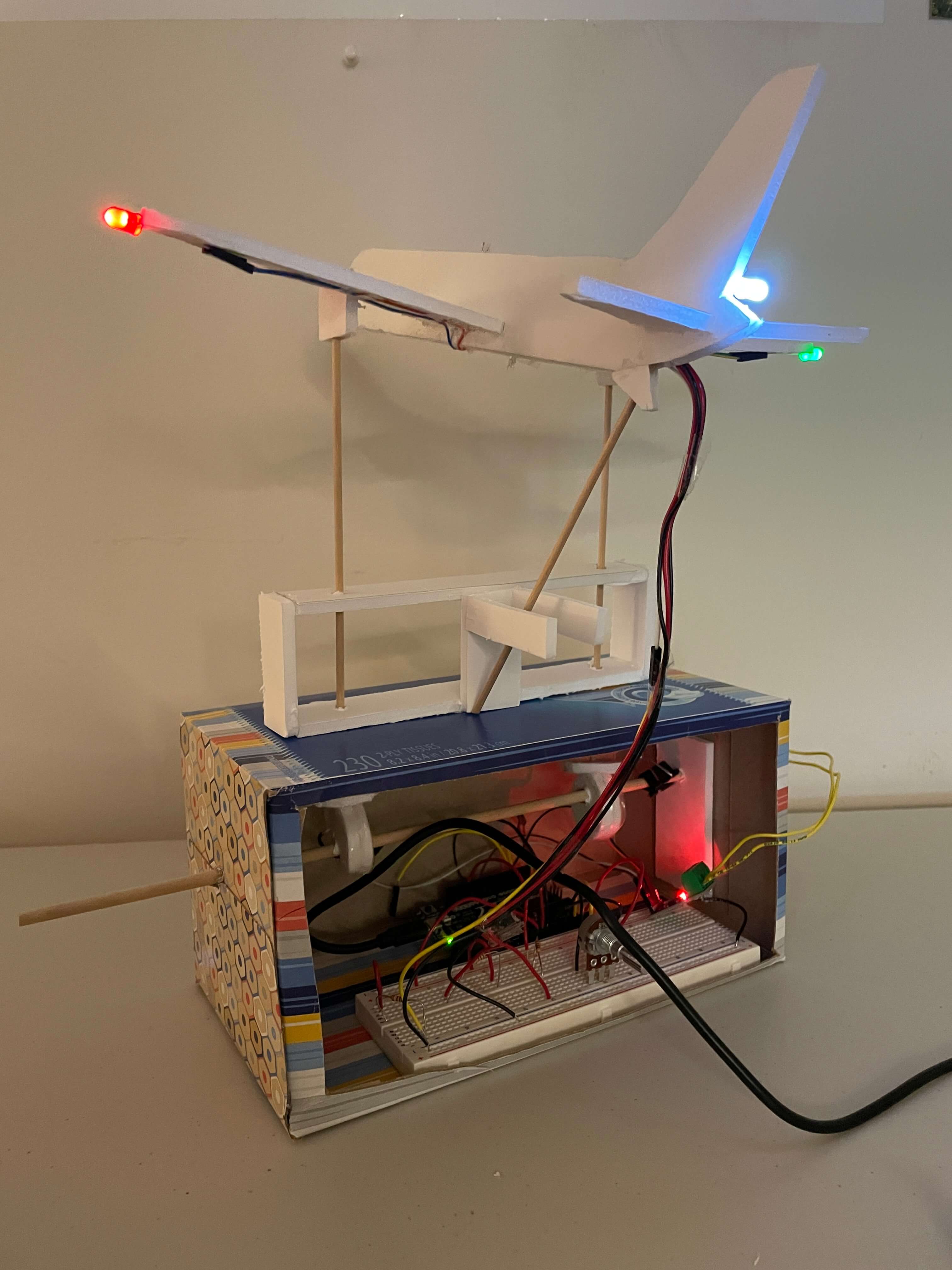
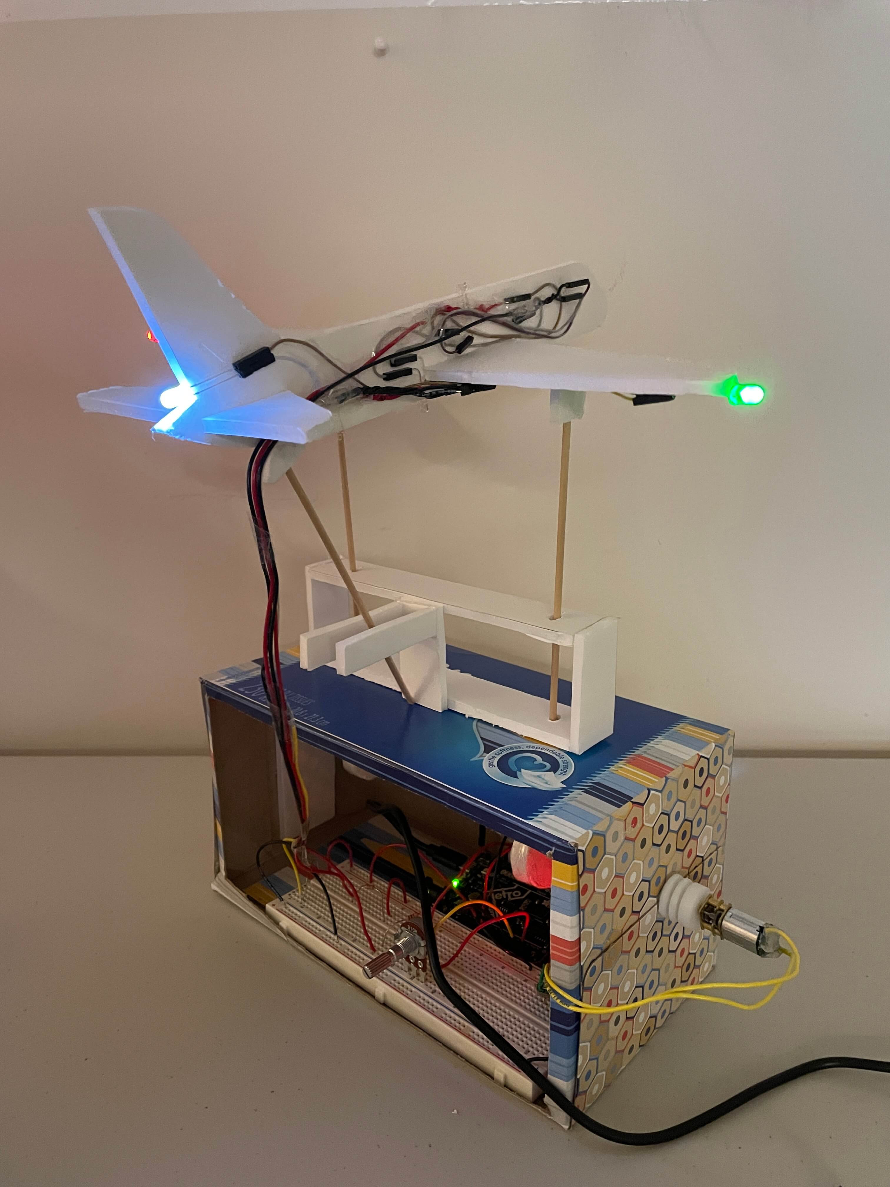
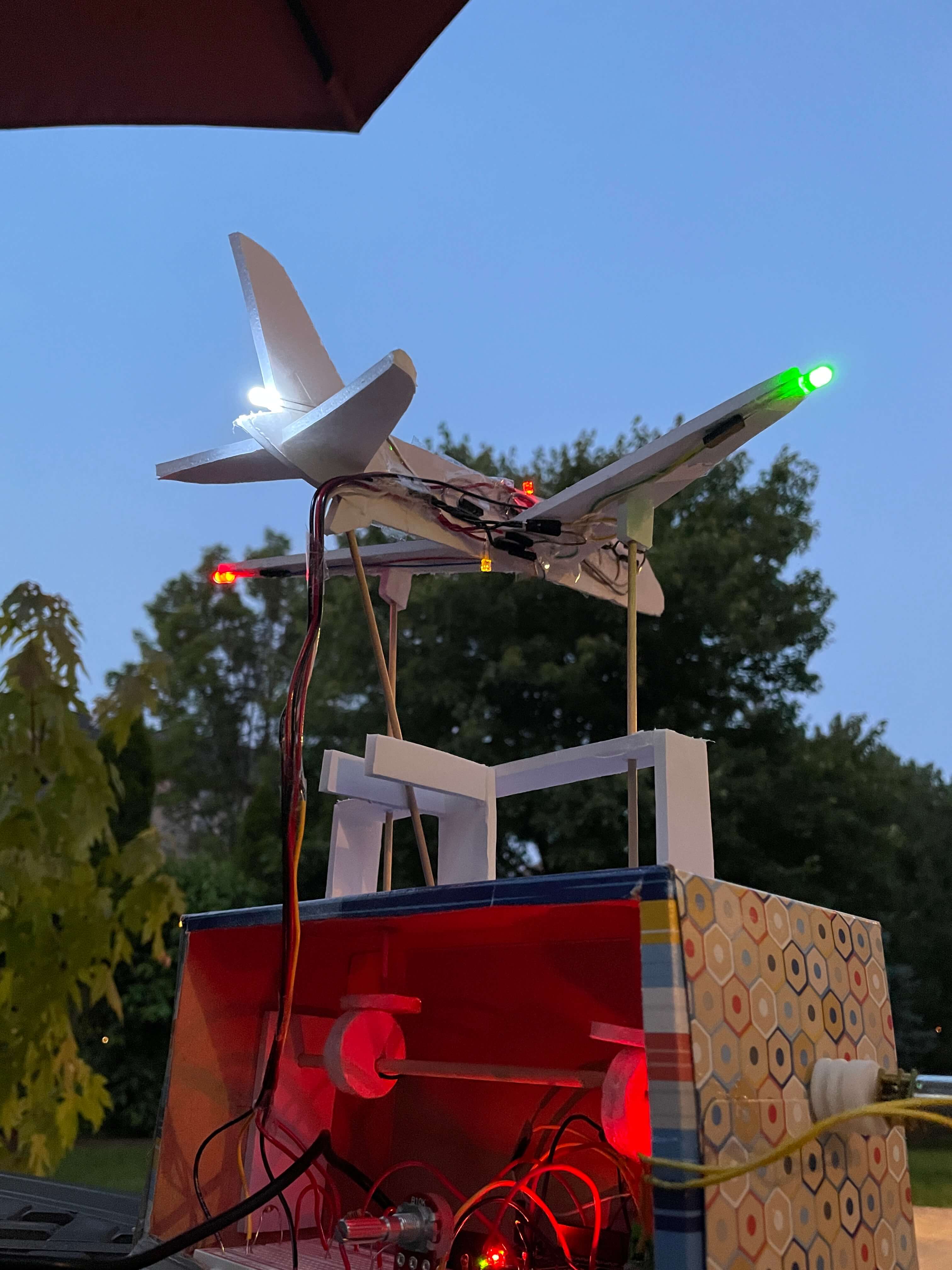
To start off with the electronics, I did a little research on plane lights. I wanted to add some lights around my plane to give it that extra flare, and so it looks really cool, especially in the dark. I found a short YouTube video that summed up what all of the outer lights mean on planes. Of course, I can't add in every light, but I wanted to add in few of the most prominent ones. I put a green LED on the right wing, a red on the left, a white by the tail, and red and yellow blinking lights on the top and bottom of the fuselage (the blinking is done in the code, which I talk about later). I'm not exactly sure how accurate the red and yellow blinking LEDs are, but they look cool and may be somewhat representative of the actual blinking lights, so I kept them on. I put images of the diagram I followed and my plane model below.

To connect all of these LEDs to the breadboard while still keeping them hidded in the main view required some outside of the box thinking (Get it? Because it's literally outside of the box. Ha!). But seriously, it was a little challenging, not because any of the wiring was complicated but because there were just so many wires.
In total, I have 4 circuits in my sculpture. One for the DC motor, and 3 others for the lights. For the lights, one circuit is for the red and green LEDs, another is for the white LED, and the third is for the blinking LEDs. The reason I split up the red-green circuit and the white circuit is because when I tested running those 3 LEDs in parallel, they didn't work. However, the red and green did run in parallel, although the green got a little dim. I have the blinking LEDs in their own circuit because they are the only ones to blink, they have their own set of code, which if connected to other circuits, would cause the other LEDs to blink too.
Having 3 LED circuits was actually helpful in wiring the plane. It means that I only have to supply 3 positive wires to the plane instead of 5 for each LED. Also, I could've technically only run one ground wire to the plane, but that would get confusing to connect to all 5 LEDs on the plane, so there are 2 ground wires, one for the red, green, and white LEDs and another for the blinking LEDs. Something to note is that the yellow wire seen on the right picture is actually a positive wire, I just didn't want to cut another positive wire from the roll when I already had a yellow one to size.
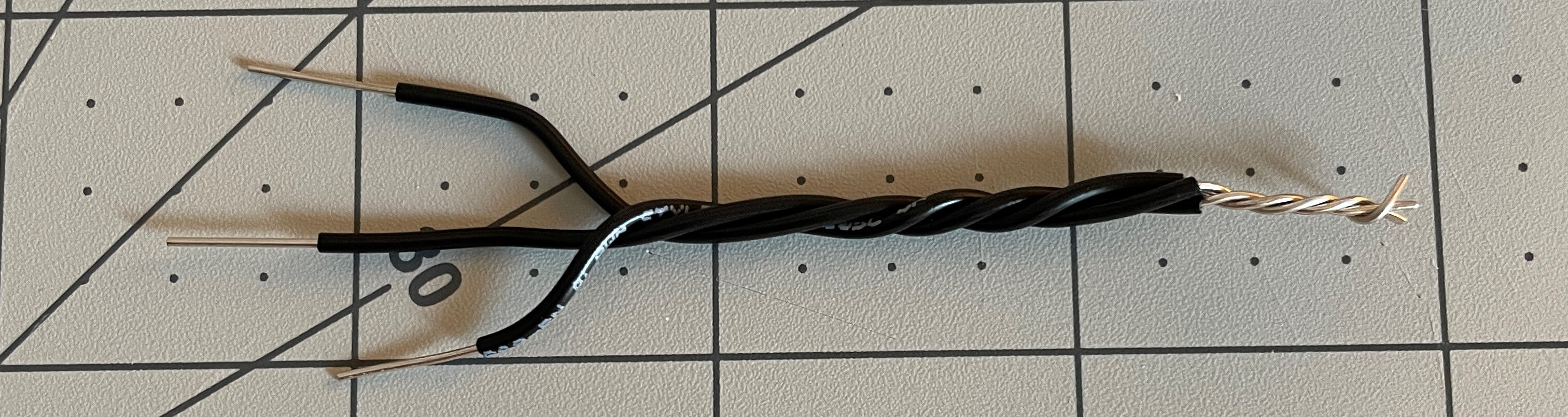
I made four makeshift "soldered" wire joints, as seen above, because I didn't want to actually solder anything. I made 1-to-2 and 1-to-3 wire joints. This saved a lot of time because I didn't have to solder wires or use extra positive and ground wires. In total, I used three 1-to-2 joints, two for positive and one for ground, and one 1-to-3 joint for ground.
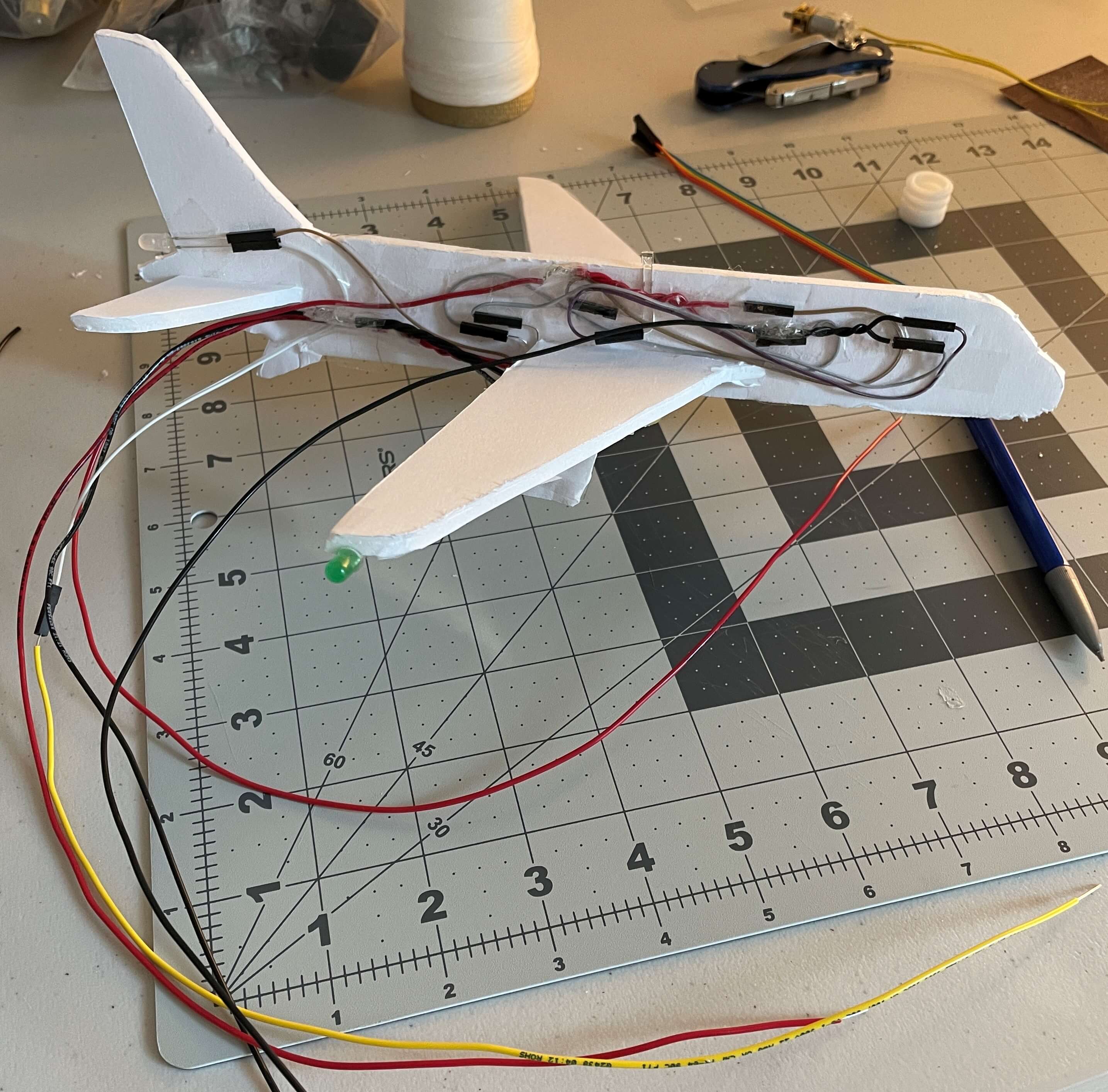
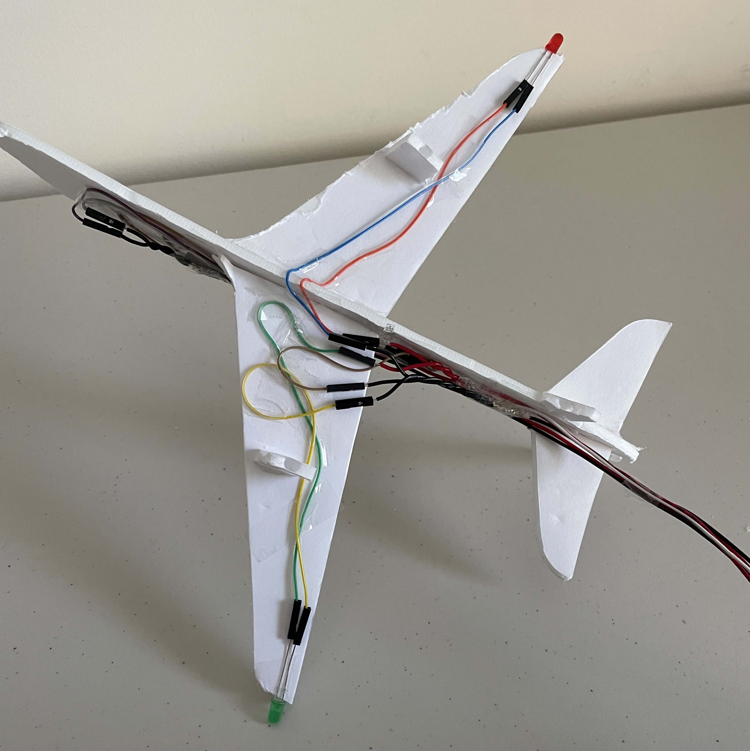
To the right are two more pictures of the wiring. Because the LEDs all have male connectors, I had to first use the female-to-female wires to first attach to the LEDs, and then use the male solid-core wire. This is the main reason why there are so many wires on the plane.
Unfortunately, because I taped on the LEDs and the wires, I can't really easily remake the whole plane with LEDs. That's why I took pictures and videos of my sculpture from every possible angle.
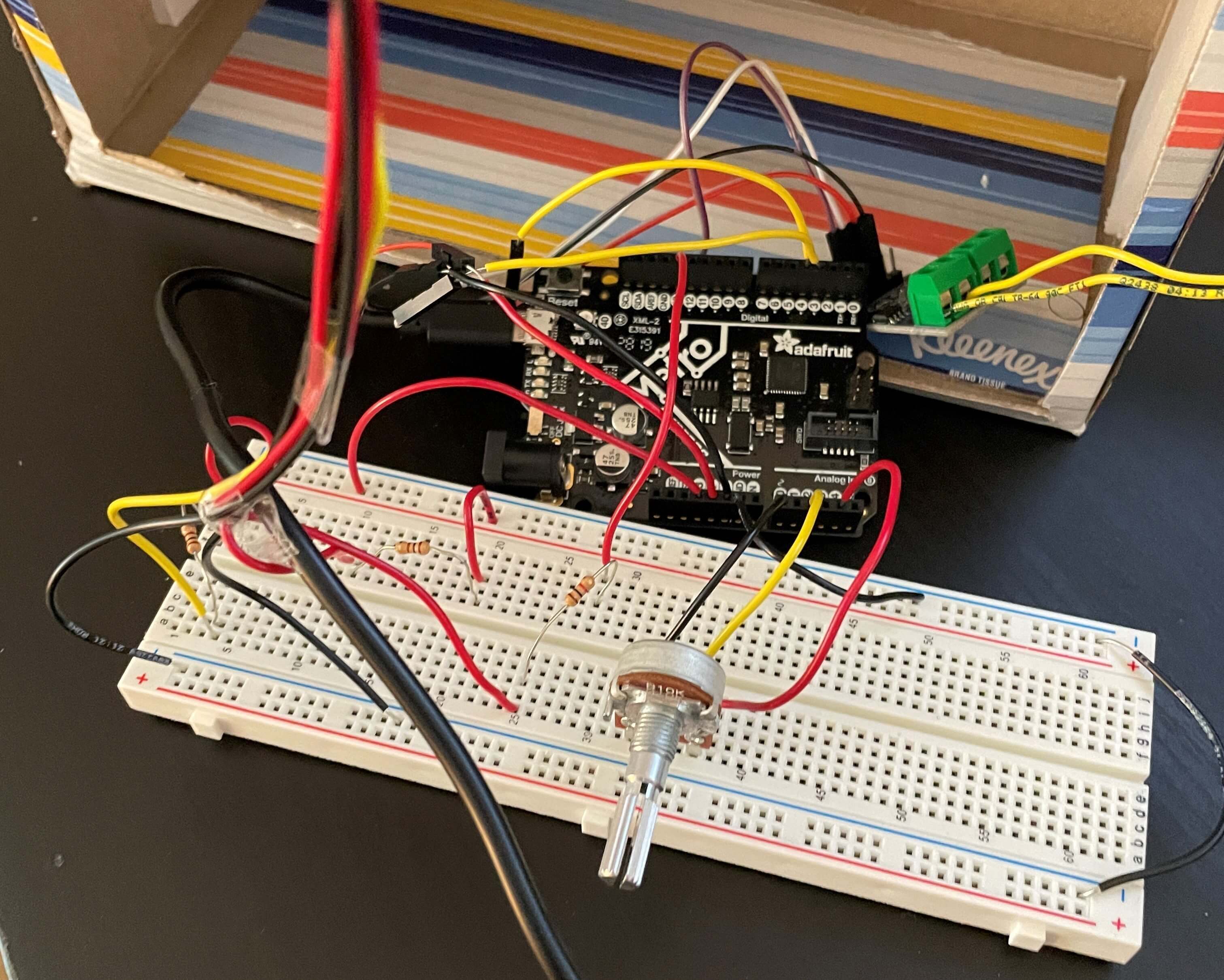
Connecting the wires up to the breadboard was simple, although a little confusing at times because of the number of wires inside of the box. Below, there are pictures of what my wiring on looks like on the breadboard and Metro board. I also added pictures of the same circuit simulated in Tinkercad further below, so it's easier to see what's happening.
Just a quick summary now, I used two 100 Ohm resistors for the red-green and white LED circuits and one 1k Ohm resistor for the blinking circuit. The potentiometer is a variable resistor itself and controls the DC motor in either direction (clockwise and counter-clockwise).
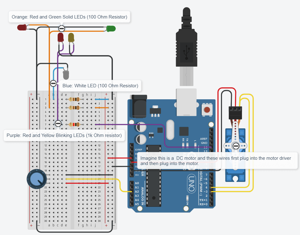
One thing to note is that on the Tinkercad diagram, because the motor drivers we use aren't on Tinkercad, I didn't use any drivers. Also, there are DC motors on Tinkercad, but because I wanted to show the yellow PWM wires also connecting to the motor (the DC motor only has positive and ground), I used a servo motor, which has positive, ground, and PWM. So as annotated, pretend that the two yellow wires from pins 3 and 4 are connected to a motor driver and then connect to a DC motor. Do the same with the 5V and ground wires. Another thing, on the Arduino UNO board, pin 4 isn't PWM, but on the Metro board it is. I wanted to keep this diagram as accurate as I could, so I used pins 3 and 4 to connect the PWM motor wires. Either way, only the LED circuits simulate properly, as the servo motor is not coded in and the wiring for PWM is wrong.
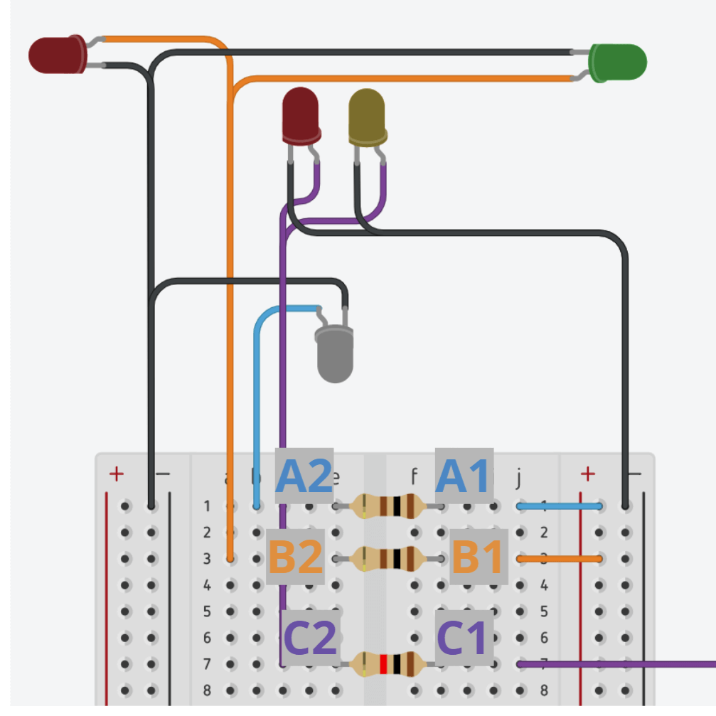
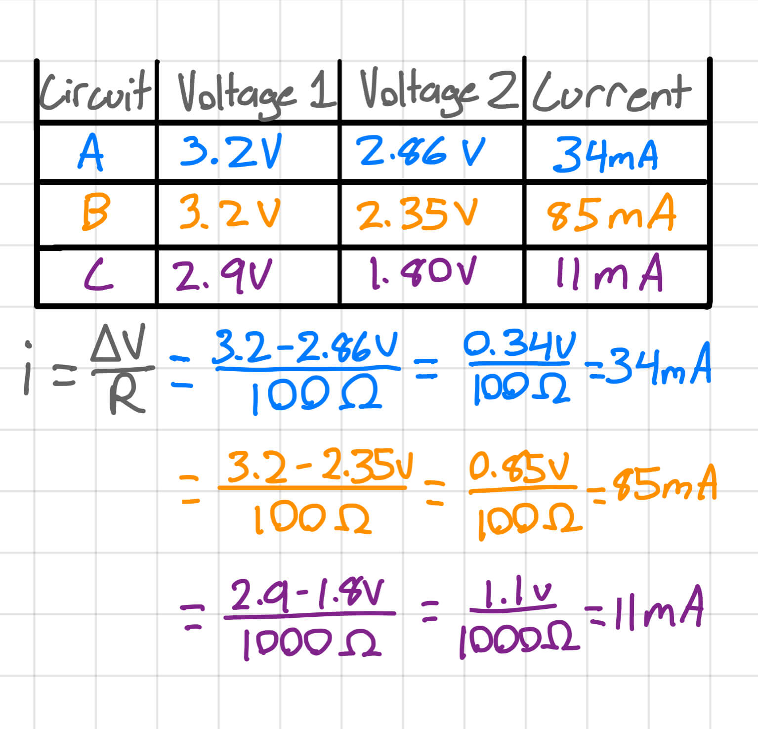
To measure the current for the 3 LED circuits, I used a multimeter before and after the resistor of each circuit. Below, there is a diagram of where I measured voltage on the LED circuits and a chart of the currents in each circuit. I made the diagram using a picture of the Tinkercad circuit, and I made the chart using Goodnotes 5 on my iPad.
The range of currents for all the circuits is 74mA, which isn't that much. The initial voltages for circuit A and B (the non-blinking ones) are 3.2V, while for C it's 2.9V. The voltages at point 2 vary depending upon the type and number of LED(s) that are on the circuit. For example, on circuit A, there is only one white LED, so the voltage for point 2 is higher than the voltage for point 2 in the other circuits. In circuit B, there are two LEDs, one green and one red, so the voltage is between that of circuit A and C. For circuit C, the initial voltage is 2.9V, which is less than the others because circuit C is getting power from pin 13, whereas the other circuits are getting power from the 3.3V pin. As expected, the voltage at point 2 for circuit C is the lowest out of the voltages all the circuits at 1.8V. This is mainly due to using the 1k Ohm resistor for circuit C, and using 100 Ohm resistors for A and B.
Doing all the wiring was definitely a bit of a headache because of how many wires there were, but it was overall worth it because of the end result. I think the plane with LEDs turned out really well and adds a lot to the effect of it seeming like an actual plane, instead of just a piece of moving foamboard. Next, I talk about all of the coding I did to make everything work.
The Programming Build Process
For the coding part of my sculpture, I coded about 30% of the full code, and the rest was either from an earlier lab or from code I found online. The biggest challenge when it came to coding was figuring out how to not use a delay() function for the LEDs, as a delay function would mess up the looped code for the motor. I wanted the motor and the LEDs to work synchronously, and I was able to do so by doing some research on how to use the millis timer. I also watched a few youtube videos to learn how to use the millis timer and the basics of Arduino coding in general. The second video explains how to use the millis timer really well, so I'd recommend watching it if you want to learn more about my code.
Just a reminder, for the Arduino code embed below, there are 3 tabs: V1, V2, and V3. You can click on each tab to change which iteration of the code is being displayed. I talk about each iteration of code below.
At this point, when plugging in the wires to the bread and Metro boards, all of the LEDs turned on (none blinking) and the motor constantly turned in a clockwise direction. I fixed the motor problem first by using the potentiometer motor control code we used in lab last week. This made it so the motor turned in either direction, which I wanted. This is represented in the V1 code tab.
Next, I wanted to add the blink code so that the top and bottom LEDs blinked. But, one issue I ran into was the delay() function in the blink command messed with the code for the motor. I searched online for alternatives to the delay function, and I found many helpful youtube videos as well as code from Arduino themselves. On the Arduino code editor, there is actually an example sketch of Blink Without Delay. As the name suggests, this is code for LEDs to blink without the use of the delay function. I copied the example code and formatted it to fit my code.
Looking at the V2 code tab, the way the millis() timer works in a nutshell is by first starting a timer that counts in milliseconds. Then, every 1000 millisecds, 1 second, the LED turns either on or off, which is the blink function. Lines 41 to 51 in the V2 page is where the timer code is. The millis() timer runs forever, which is why I used the unsigned long variable. Unsigned long variables store 32 bits of info, which is 16 more than regular int variables hold. Also, it only stores positive numbers, so the range, for my usage, is virtually unlimited. So, everytime the timer reaches or passes the 1000 millisecond interval, the LED switches states and the previous time is set equal to the current time. It sounds more confusing than it really is, which is why I recommend watching this video for a better explanation. I talk about why I added the V3 page below.
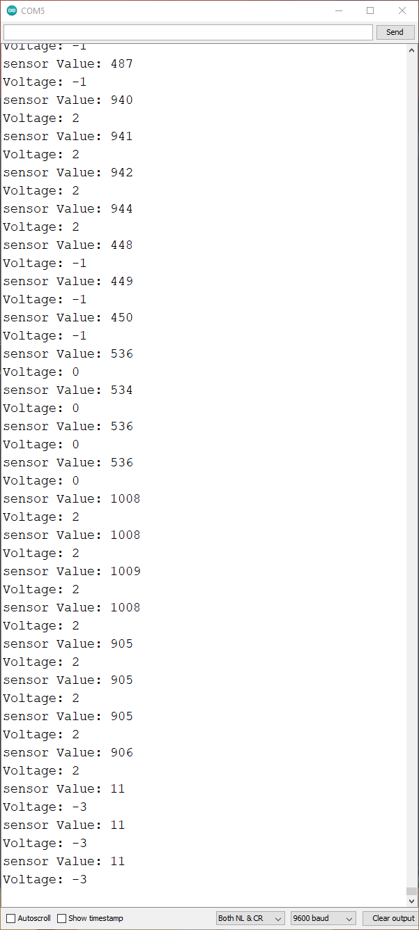
In version 2.5, let's call it, I added in a serial monitor to measure the voltage of the potentiometer. I got it to work, but I needed to add some sort of delay or else the serial monitor would spit out literally as many numbers as it virtually could. This can be seen in the first picture below, where the serial monitor would spew out 3 to 4 values at once instead of 1 at a time. So, my first idea was to just use the same millisecond timer I already had. Now, this works completely fine, and the delay between each read is 1 second. However, I wanted to have them independent of eachother, meaning I wanted to change the time of one and not have it affect the other. This was confusing at first, but with the help of the TA during the last lab, I learned that I needed to create a completely seperate timer for this to work.
One thing to note is that I actually made an error in the first image to the right. I made the voltage readings go from a scale of -3 to 3, which is incorrect. It should be from a scale of 0 to 3.
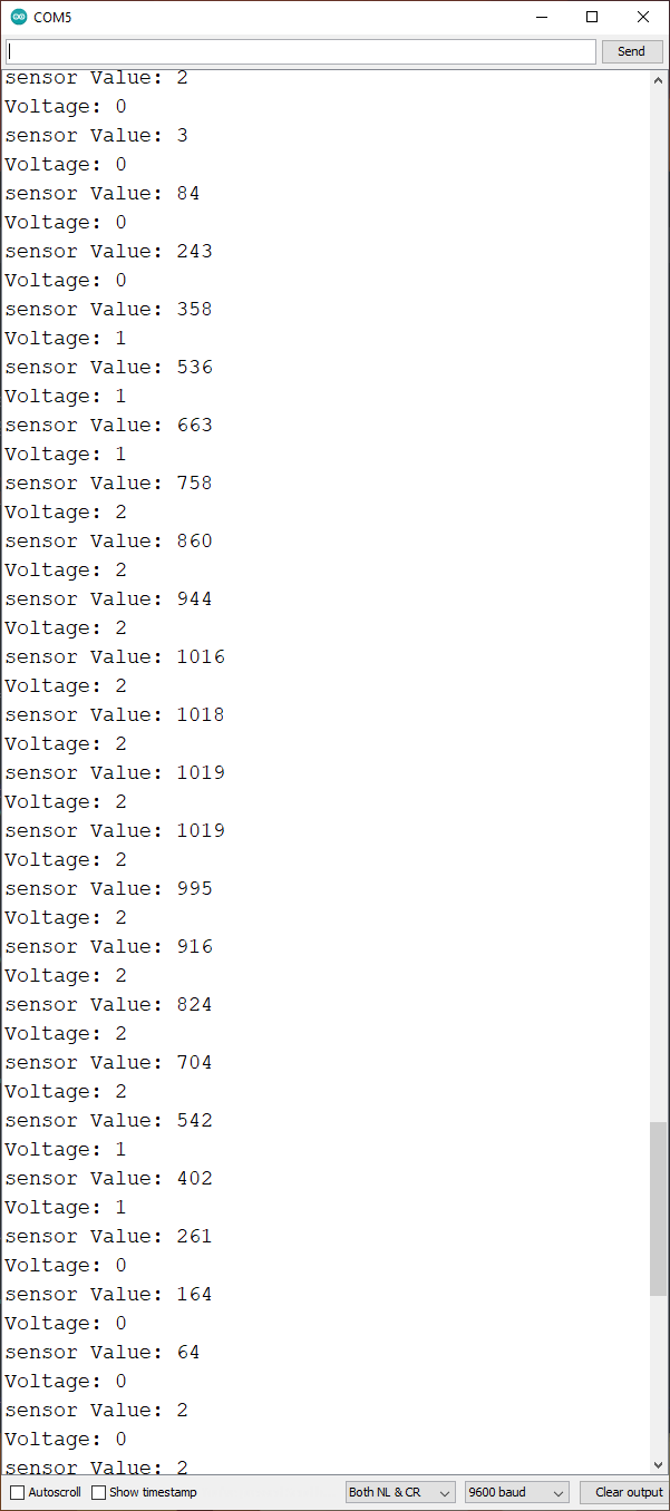
As seen in the V3 tab, all I did was duplicate the first set of code and change the variables by adding a "2" after them to make a second timer. This was very easy, as the code was already written. The finished result is seen on the far right, where the serial monitor works perfectly and the time interval between each read can be adjusted independently of the other millisecond timer.
One odd discovery I found with the potentiometer using the serial monitor is that the voltage doesn't ever go the 0 or 1023. The lowest it goes is 2, and the highest is about 1020. Also, the voltage write doesn't ever go to 3. I'm not exactly sure why, as before, on other circuits with just the potentiometer, the serial monitor read from 0 to 1023. I tried troubleshooting by unplugging the motor to see if that was the problem, but the same problem still persisted.
Final Product
That's all there was to it: the structure, electrical, and coding elements. I think the final product turned out great, especially with all of the LEDs. The rest of this page is just pictures, gifs, and videos. I also took the sculpture outside to take some evening shots.


What I Learned
» Why using the delay() function doesn't work with simultaneously functioning components
» How to use the millis() function
» When to use the millis() function
» How to create a timer using the millis() function
» How to create a blink circuit without the delay() function
» How to troubleshoot issues with the millis() function